Layer 3 VPN Configurations
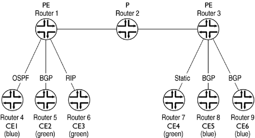
These configurations illustrate a typical Layer 3 VPN scenario. Router 4, Router 8, and Router 9 belong to one VPN site named blue. Router 5, Router 6, and Router 7 belong to another VPN site named green. The PE-CE protocols could be BGP, static route (with the next hop configured toward the attached PE), or an IGP such as OSPF or RIP. The PE-PE connections are running MBGP. Labelled VPN routes are exchanged over the MBGP sessions that terminate on the PE routers.
The topology shown in Figure 14.12 is used in these configurations.
Figure 14.12. Layer 3 VPN Topology

Router 1 Configuration
interfaces { fe-0/0/0 { description ...Get Juniper Networks® Field Guide and Reference now with the O’Reilly learning platform.
O’Reilly members experience books, live events, courses curated by job role, and more from O’Reilly and nearly 200 top publishers.

