Chapter 1. Juniper QFX10000 Hardware Architecture
There’s always something a little magical about things that are developed and made in-house. Whether it’s a fine Swiss watch with custom movements or a Formula 1 race car, they were built for one purpose: to be the best and perform exceptionally well for a specific task. I always admire the engineering behind such technology and how it pushes the limits of what was previously thought impossible.
When Juniper set out to build a new aggregation switch for the data center, a lot of time was spent looking at the requirements. Three things stood out above the rest:
- High logical scale
- New data center architectures such as collapsing the edge and aggregation tiers or building large hosting data centers require a lot of logical scale such as the number of host entries, route prefixes, access control lists (ACL), and routing instances.
- Congestion control
- Given the high density of 40/100GbE ports and collapsing the edge and aggregation tiers into a single switch, a method for controlling egress congestion was required. Using a mixture of Virtual Output Queuing (VOQ) and large buffers guarantees that the traffic can reach its final destination.
- Advanced features
- Software-Defined Networks (SDNs) have changed the landscape of data center networking. We are now seeing the rise of various tunneling encapsulations in the data center such as Multiprotocol Label Switching (MPLS) and Virtual Extensible LAN (VXLAN). We are also seeing new control-plane protocols such as Open vSwitch Database Management Protocol (OVSDB) and Ethernet VPN (EVPN). If you want to collapse the edge into the aggregation switch, you also need all of the WAN encapsulations and protocols.
Combining all three of these requirements into a single switch is difficult. There were no off-the-shelf components available to go build such a high-performance and feature-rich switch. Juniper had to go back to the whiteboard and design a new network processer specifically for solving the switching challenges in the modern data center.
This is how the new Juniper Q5 network processor was born.
Network Processors
Network processors are just a type of application-specific integrated circuit (ASIC). There is a very large range of different types of ASICs that vary in functionality, programmability, and speed, as shown in Figure 1-1.
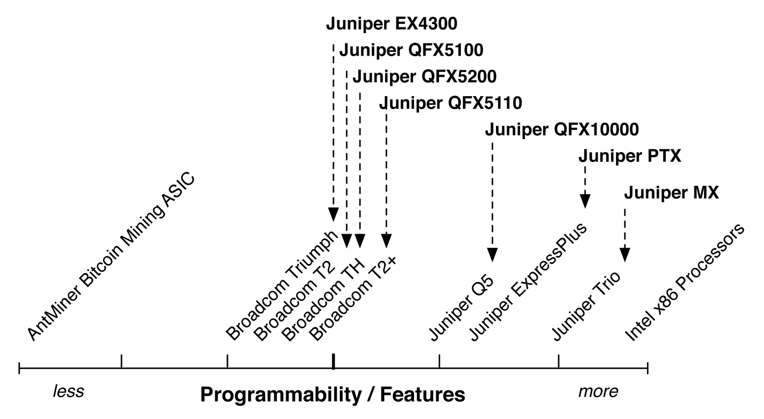
Figure 1-1. Line graph of programmability versus features of ASICs
There are many factors to consider in an ASIC. At a high level, it’s easy to classify them in terms of programmability. For example, if all you need to do is mine Bitcoins, the AntMiner ASIC does this very well. The only downside is that it can’t do anything else beyond mine Bitcoins. On the flip side, if you need to perform a wide range of tasks, an Intel x86 processor is great. It can play games, write a book, check email, and much more. The downside is that it can’t mine Bitcoins as fast as the AntMiner ASIC, because it isn’t optimized for that specific task.
In summary, ASICs are designed to perform a specific task very well, or they are designed to perform a wide variety of tasks but not as fast. Obviously there is a lot of area between these two extremes, and this is the area into which most of the network processors fall. Depending on the type of switch, it will serve a specific role in the network. For example, a top-of-rack (ToR) switch doesn’t need all of the features and speed of a spine or core switch. The Juniper ToR switches fall more toward the left of the graph, whereas the Juniper QFX10000, Juniper PTX, and Juniper MX are more toward the right. As you move from the spine of the network into the edge and core, you need more and more features and programmability.
Another important attribute to consider is the amount of logical scale and packet buffer. Depending on the type of switch and use case, you might need more or less of each. Generally, ToR switches do not require a lot of scale or packet buffer. Spine switches in the data center require a lot more logical scale because of the aggregation of the L2 and L3 addressing. The final example is that in the core and backbone of the network, all of the service provider’s customer addressing is aggregated and requires even more logical scale, which is made possible by the Juniper MX, as illustrated in Figure 1-2.
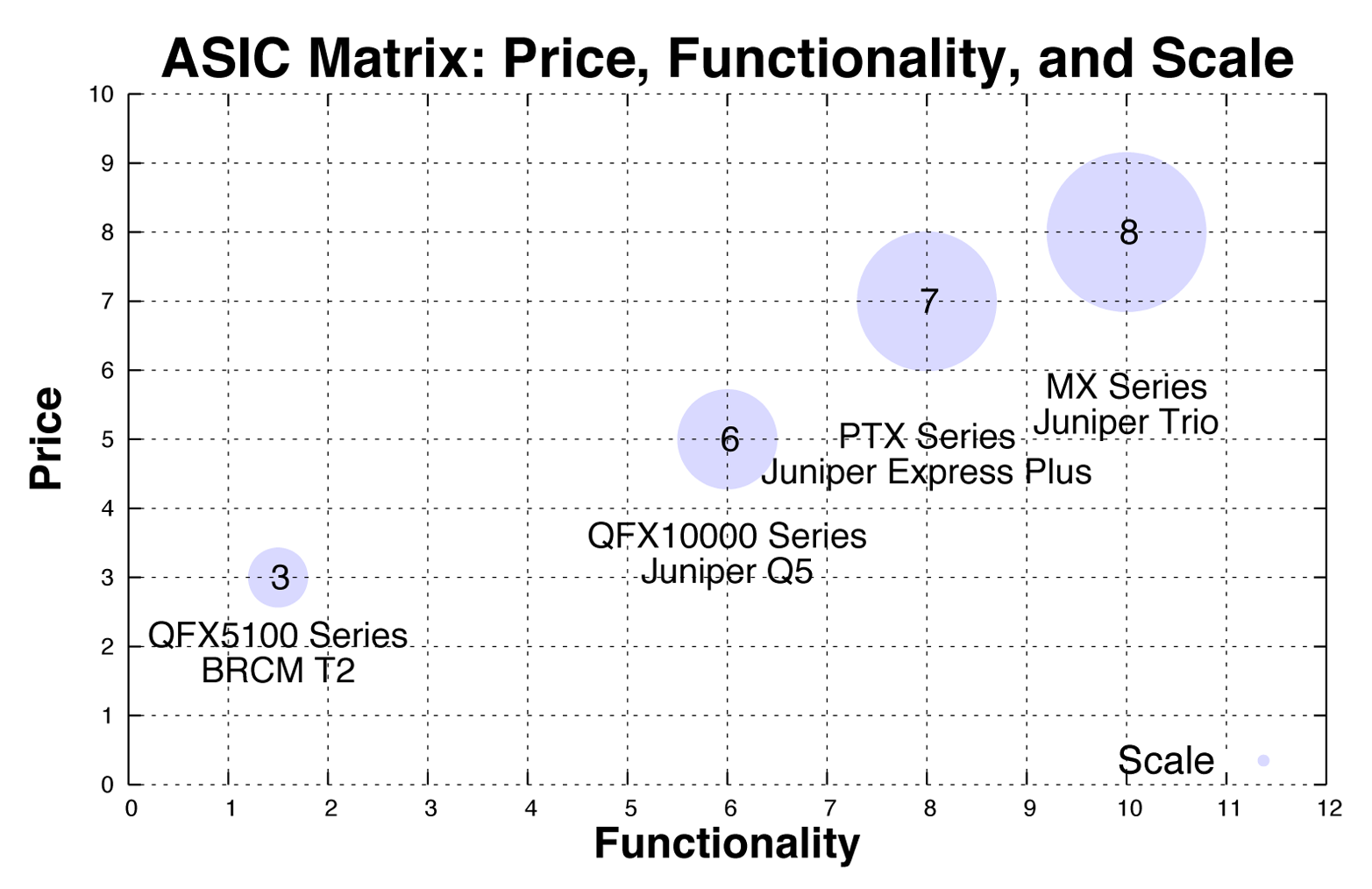
Figure 1-2. Juniper matrix of price, functionality, and scale
The goal of the QFX10000 was to enable the most common use cases in the fabric and spine of the data center. From a network processor point of view, it was obvious it needed to bridge the gap between Broadcom T2 and Juniper Trio chipsets. We needed more scale, buffer, and features than was available in the Broadcom T2 chipset, and less than the Juniper Trio chipset. Such a combination of scale, features, and buffer wasn’t available from existing merchant silicon vendors, so Juniper engineers had to create this new chipset in-house.
The Juniper Q5 Processor
The Juniper Q5 network processor is an extremely powerful chipset that delivers high logical scale, congestion control, and advanced features. Each Juniper Q5 chip is able to process 500Gbps of full duplex bandwidth at 333 million packets per second (Mpps). There are three major components to the Juniper Q5 chipset (Figure 1-3):
-
Front panel ports
-
Packet processing
-
Fabric interfaces
The front panel ports are the ports that are exposed on the front of the switch or line card for production use. Each Juniper Q5 chip can handle up to 5x100GbE, 12x40GbE, or 48x10GbE ports.
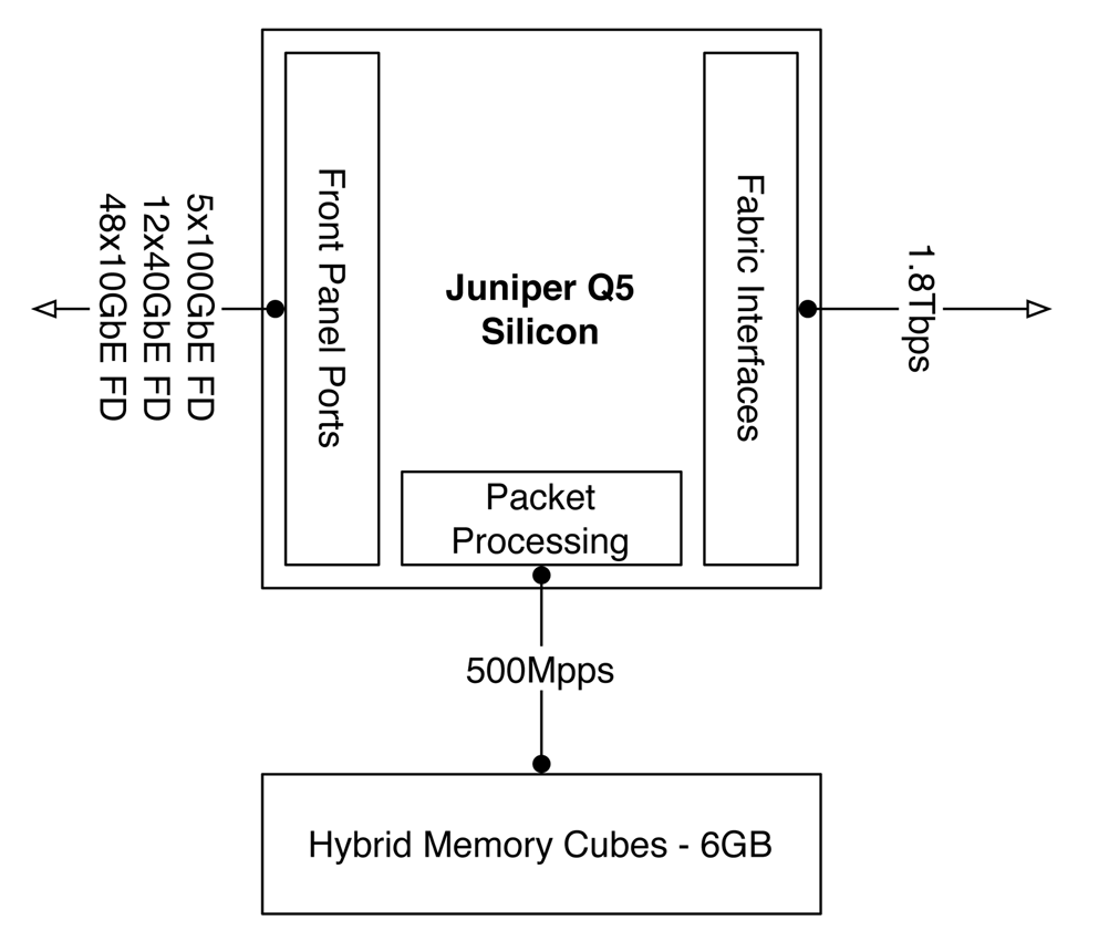
Figure 1-3. Juniper Q5 chipset architecture
The packet processing is able to handle up to 500 Mpps within a single chip so that packets can be looped back through the chipset for additional processing. The overall chip-to-chip packet processing is able to handle 333 Mpps. For example, the Juniper QFX10002-72Q switch has a total of six Juniper Q5 chips, which brings the total system processing power to 2 billion packets per second (Bpps).
The Juniper Q5 chipsets have been designed to build very dense and feature-rich switches with very high logical scale. Each switch is built using a multichip architecture; traffic between Juniper Q5 chips are cellified and sprayed across a switching fabric.
Front Panel Ports
Each Juniper Q5 chip is tri-speed; it supports 10GbE, 40GbE, and 100GbE. As of this writing, the IEEE still hasn’t ratified the 400GbE MAC so the Juniper Q5 chip is unable to take advantage of 400GbE. However, as soon as the 400GbE MAC is ratified, the Juniper Q5 chip can be quickly programmed to enable the 400GbE MAC.
Packet Processing
The heart of the Juniper Q5 chipset is the packet processor. The packet processor is responsible for inspecting the packet, performing lookups, modifying the packet (if necessary), and applying ACLs. The chain of actions the packet processor performs is commonly referred to as the pipeline.
The challenge with most packet processors is that the packet processing pipeline is fixed in nature. This means that the order of actions, what can be done, and performance is all very limited. A limited packet processing pipeline becomes a challenge when working with different packet encapsulations. For example, think about all of the different ways a VXLAN packet could be processed:
-
Applying an ACL before or after the encapsulations or decapsulation
-
Requiring multiple destination lookups based on inner or outer encapsulations
-
Changing from one encapsulation to another, such as VXLAN to MPLS
The Juniper Q5 chipset was designed to solve these challenges from the beginning. The key is creating a flexible packet processing pipeline that’s able to process packets multiple ways at any stage through the pipeline without a loss in performance. Figure 1-4 illustrates this pipeline.
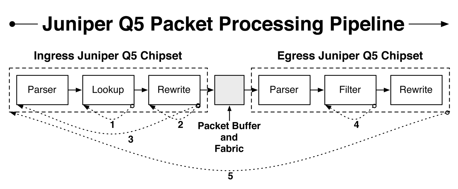
Figure 1-4. The Juniper Q5 packet processing pipeline
The Juniper Q5 packet processing pipeline is divided into two parts: the ingress and egress chipsets. The Juniper Q5 chipsets communicate with one another through a fabric that is interconnected to every single Juniper Q5 chipset. The ingress chipset is mainly responsible for parsing the packet, looking up its destination, and applying any type of tunnel termination and header rewrites. The egress chipset is mainly responsible for policing, counting, shaping, and quality of service (QoS). Notice Figure 1-4 has five loopbacks throughout the pipeline. These are the flexible points of recirculation that are enabled in the Juniper Q5 chipset and which make it possible for the Juniper QFX10000 switches to handle multiple encapsulations with rich services. Let’s walk through each of these recirculation points, including some examples of how they operate:
-
There are various actions that require recirculation in the lookup block on the ingress Juniper Q5 chipset. For example, tunnel lookups require multiple steps: determine the Virtual Tunnel End-Point (VTEP) address, identify the protocol and other Layer 4 information, and then perform binding checks.
-
The ingress Juniper Q5 chipset can also recirculate the packet through the rewrite block. A good example is when the Juniper QFX10000 switch needs to perform a pair of actions such as (VLAN rewrite + NAT) or (remove IEEE 802.1BR tag + VLAN rewrite).
-
The packet can also be recirculated through the entire ingress Juniper Q5 chipset. There are two broad categories that require ingress recirculation: filter after lookup and tunnel termination. For example, ingress recirculation is required when you need to apply a loopback filter for host-bound packets or apply a filter to a tunnel interface.
-
The egress Juniper Q5 chipset can perform multiple actions. For example, it can count packets, police packets, or apply software traps.
-
Finally, the entire packet is able to recirculate through the entire ingress and egress Juniper Q5 packet processing pipeline multiple times, as well. The main purpose is to support multicast replication tree traversal.
The Juniper Q5 packet processing pipeline is a very powerful and flexible mechanism to enable rich tunnel services, packet filtering, multicast, network services, and QoS. The pipeline is programmable and can be upgraded through each Juniper software release to support new features and further increase performance and efficiency.
Fabric Interfaces
Each Juniper Q5 chipset has a set of fabric interfaces that are used to connect it to a Juniper fabric chip that lets it have full bisectional bandwidth to every other Juniper Q5 chipset within the switch, as depicted in Figure 1-5.
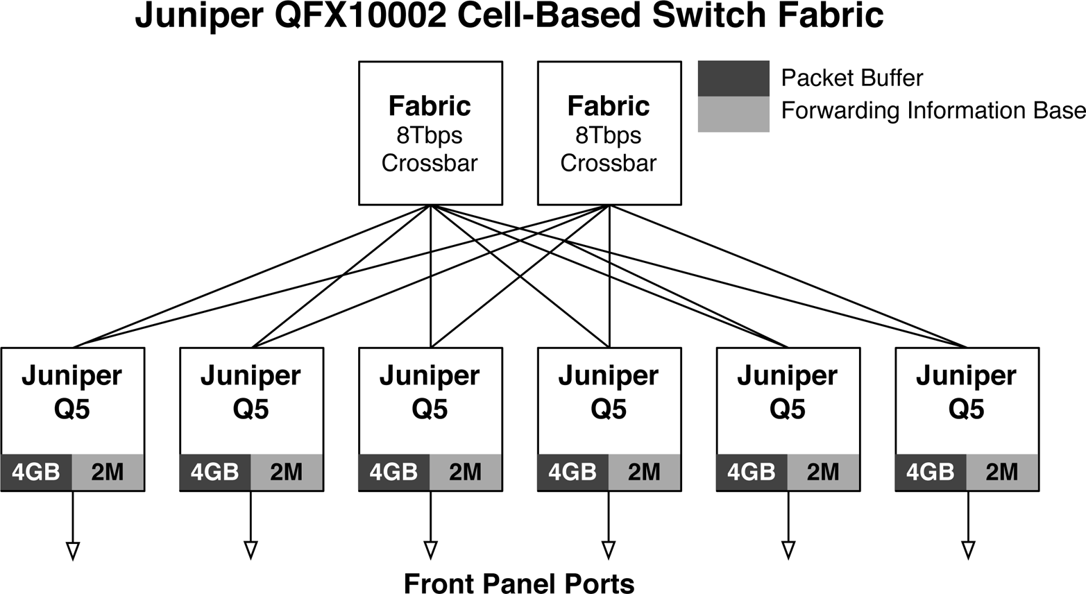
Figure 1-5. Juniper QFX10002 cell-based switching fabric
The Juniper QFX10002-72Q has a total of six Juniper Q5 chipsets to support the 72x40GbE interfaces. Each of the Juniper Q5 chipsets are connected together in a Clos topology using a pair of Juniper fabric chips that can each support up to 8Tbps of bandwidth. There are two major design philosophies when it comes to building a multiple chipset switch:
-
Packet-based fabrics
-
Cell-based fabrics
Packet-based fabrics are the easiest method to implement a multichip switch. It simply forwards all traffic between the chipsets as native IP. Both the front panel chips and fabric chips can utilize the same underlying chipset. However, the drawback is that packet-based fabrics are not very good at Equal-Cost Multipath (ECMP) and are prone to head-of-line blocking. This is because in a packet-based fabric, each chipset will fully transmit each packet—regardless of size—across the switch. If there are large or small flows, they will be hashed across the fabric chips according to normal IP packet rules. As you can imagine, this means that fat flows could be pegged to a single fabric chip and begin to overrun smaller flows. Imagine a scenario in which there are multiple chips transmitting jumbo frames to a single egress chip. It would quickly receive too much bandwidth and begin dropping packets. The end result is that ECMP greatly suffers and the switch loses significant performance at loads greater than 80 percent, due to the head-of-line blocking.
The alternative is to use a cell-based fabric, which uniformly partitions ingress packets into cells of the same size. For example, a 1000-byte packet could be split up into 16 different cells which have a uniform size of 64 bytes each. The advantage is that large IP flows are broken up into multiple cells that can be load balanced across the switching fabric to provide nearly perfect ECMP.
Traditionally, cells are fixed in size, which creates another problem in packing efficiency, often referred to as cell tax. Imagine a scenario in which there was a 65-byte packet, but the cell size was 64 bytes. In such a scenario, two cells would be required; the first cell would be full, whereas the second cell would use only one byte. To overcome this problem, the Juniper Q5 chipset cell size can vary depending on the overall load of the switch to achieve better packing efficiency. For example, as the overall bandwidth in the switch increases, the cell size can dynamically be increased to transmit more data per cell. The end result is that a cell-based fabric offers nearly perfect ECMP and can operate at 99 percent capacity without dropping packets.
The Juniper Q5 chipset uses a cell-based fabric with variable cell sizes to transmit data among the different Juniper Q5 chipsets. Each model of the QFX10000 switches uses the cell-based fabric technology, including the fixed QFX10002 switches.
Juniper QFX10002 fabric walk-through
Let’s take a look at some of the detailed information about the fabric from the command line on the QFX10002. Keep in mind that the Juniper QFX10002; can have either one or two fabric chips, and either three or six Packet Forwarding Engines (PFEs). For example, the QFX10002-36Q has three PFEs with a single fabric chip; and the QFX10002-72Q has two fabric chips and six PFEs as shown in Figure 1-5. The reason for this is that the QFX10002-36Q is exactly half the size of the QFX10002-72Q, so it requires exactly half the number of resources.
In the following QFX10002 examples, we’ll execute all the commands from a Juniper QFX10002-72Q that has two fabric chips and six PFEs.
Let’s begin by verifying the number of fabric chips:
dhanks@qfx10000-02> show chassis fabric plane-location local
------------Fabric Plane Locations-------------
SIB            Planes
 0             0    1
Now let’s get more detailed information about each fabric chip:
dhanks@qfx10000-02> show chassis fabric sibs
Fabric management SIB state:
SIB #0  Online
    FASIC #0 (plane 0) Active
        FPC #0
            PFE #0  : OK
            PFE #1  : OK
            PFE #2  : OK
            PFE #3  : OK
            PFE #4  : OK
            PFE #5  : OK
    FASIC #1 (plane 1) Active
        FPC #0
            PFE #0  : OK
            PFE #1  : OK
            PFE #2  : OK
            PFE #3  : OK
            PFE #4  : OK
            PFE #5  : OK
Now we can begin to piece together how the PFEs are connected to the two fabric chips. Use the following command to see how they’re connected:
dhanks@qfx10000-02> show chassis fabric fpcs local
Fabric management FPC state:
FPC #0
    PFE #0
        SIB0_FASIC0 (plane  0)   Plane Enabled, Links OK
        SIB0_FASIC1 (plane  1)   Plane Enabled, Links OK
    PFE #1
        SIB0_FASIC0 (plane  0)   Plane Enabled, Links OK
        SIB0_FASIC1 (plane  1)   Plane Enabled, Links OK
    PFE #2
        SIB0_FASIC0 (plane  0)   Plane Enabled, Links OK
        SIB0_FASIC1 (plane  1)   Plane Enabled, Links OK
    PFE #3
        SIB0_FASIC0 (plane  0)   Plane Enabled, Links OK
        SIB0_FASIC1 (plane  1)   Plane Enabled, Links OK
    PFE #4
        SIB0_FASIC0 (plane  0)   Plane Enabled, Links OK
        SIB0_FASIC1 (plane  1)   Plane Enabled, Links OK
    PFE #5
        SIB0_FASIC0 (plane  0)   Plane Enabled, Links OK
        SIB0_FASIC1 (plane  1)   Plane Enabled, Links OK
As you can see, each PFE has a single connection to each of the fabric chips. The Juniper QFX10002 uses an internal Clos topology of PFEs and fabric chips to provide non-blocking bandwidth between all of the interfaces as shown in Figure 1-5.
The Juniper QFX10000 Series
The Juniper QFX10000 family is often referred to as the Juniper QFX10K Series. At a high-level, there are four switches (see Figure 1-6):
-
Juniper QFX10002-36Q
-
Juniper QFX10002-72Q
-
Juniper QFX10008
-
Juniper QFX10016
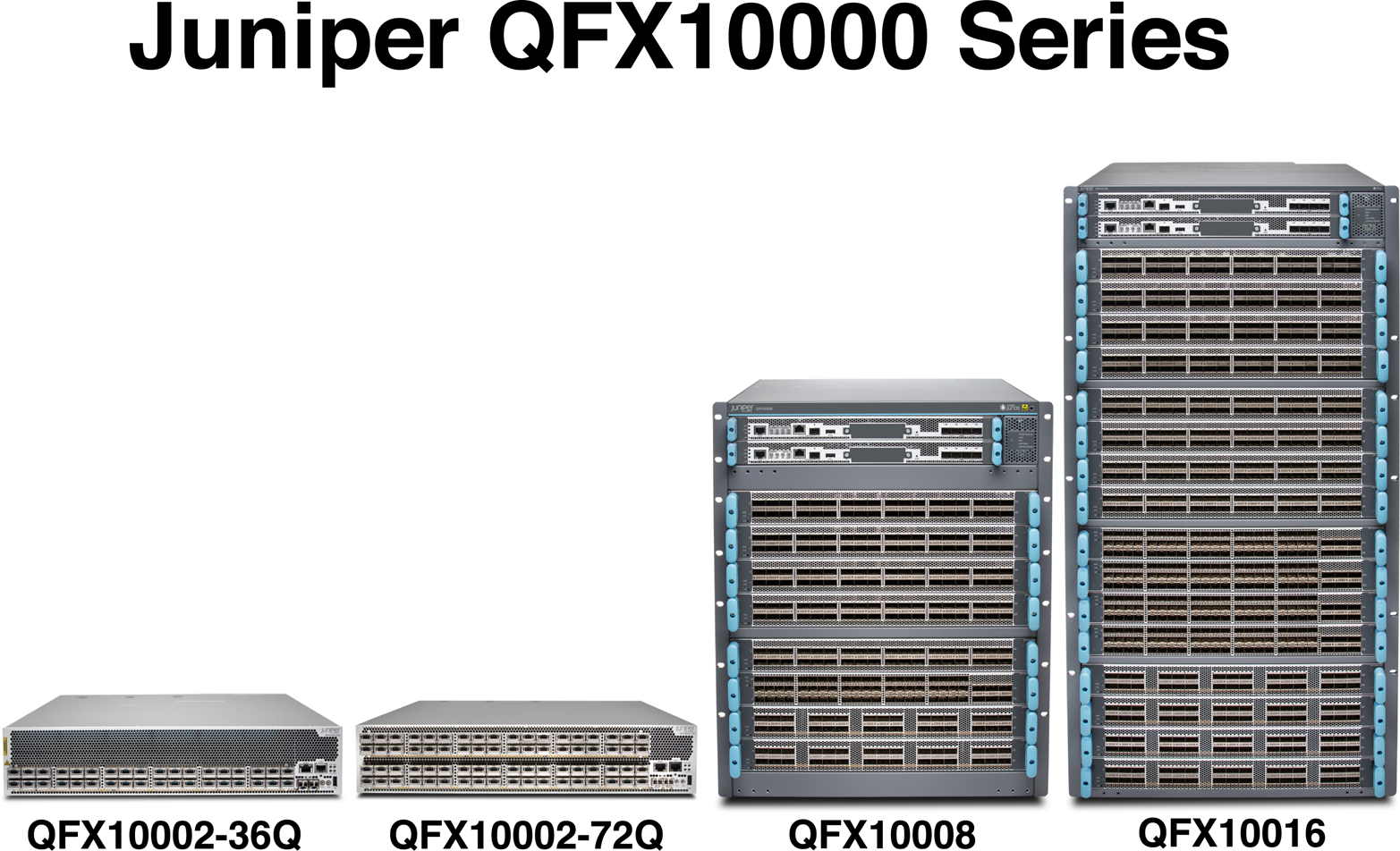
Figure 1-6. Juniper QFX10000 Series lineup
The Juniper QFX10002 model is a compact 2RU switch that comes in two port densities: 36 ports and 72 ports. The Juniper QFX10008 and QFX10016 are modular chassis switches with 8 and 16 slots, respectively.
The great thing about the Juniper QFX10K Series is that the only differences between the switches are simply the port densities. You lose no features, buffer, or logical scale between the smallest Juniper QFX10002-36Q and the largest Juniper QFX10016. Simply choose the port scale that meets your requirements; you don’t need to worry about sacrificing logical scale, buffer, or feature sets.
The Juniper QFX10K was designed from the ground up to support large-scale web, cloud and hosting providers, service providers, and Enterprise companies. The Juniper QFX10K will most commonly be found in the spine, core, or collapsed edge of a data center switching network.
Juniper QFX10K Features
The Juniper QFX10K was designed from the ground up to solve some of the most complicated challenges within the data center. Let’s take a look at some of the basic and advanced features of the Juniper QFX10K.
Layer 2
-
Full Layer 2 switching with support for up to 32,000 bridge domains.
-
Full spanning tree protocols
-
Support for the new EVPN for control plane–based learning with support for multiple data-plane encapsulations.
-
Support for virtual switches; these are similar to Virtual Routing and Forwarding (VRF) instances, but specific to Layer 2. For example, you can assign a virtual switch per tenant and support overlapping bridge domain IDs.
Automation and programmability
-
Linux operating system that’s completely open for customization
-
Support for Linux KVM, Containers (LXC), and Docker
-
Full NETCONF and YANG support for configuration changes
-
Full JSON API for configuration changes
-
Support for Apache Thrift for control-plane and data-plane changes
-
Support for OpenStack and CloudStack orchestration
-
Support for VMware NSX virtual networking
-
Support for Chef and Puppet
-
Native programming languages such as Python with the PyEZ library
-
Zero-Touch Provisioning (ZTP)
Traffic analytics
-
High-frequency and real-time traffic statistics streaming in multiple output formats, including Google ProtoBufs
-
Network congestion correlation
-
ECMP-aware traceroute and ping
-
Application-level traffic statistics using Cloud Analytics Engine (CAE)
Warning
As of this writing, some of the traffic analytics tools are roadmap features. Check with your Juniper accounts team or on the Juniper website for more information.
Juniper QFX10K Scale
The Juniper QFX10K is built for scale. There are some attributes such as firewall filters and MAC addresses that are able to distribute state throughout the entire switch on a per-PFE basis. The PFE is simply a Juniper-generic term for a chipset, which in the case of the Juniper QFX10K is the Juniper Q5 chipset. For example, when it comes to calculating the total number of firewall filters, there’s no need to have a copy of the same firewall filter in every single Juniper Q5 chip; this is because firewall filters are generally applied on a per-port basis. However, other attributes such as the Forwarding Information Base (FIB) need to be synchronized across all PFEs, and cannot benefit from distributing the state across the entire system. Table 1-1 lists all of the major physical attributes as well as many of the commonly used logical scaling numbers for the Juniper QFX10000 family.
| Attribute | QFX10K2-36Q | QFX10K2-72Q | QFX10008 | QFX10016 |
|---|---|---|---|---|
| Switch throughput | 2.88Tbps | 5.76Tbps | 48Tbps | 96Tbps |
| Forwarding capacity | 1 Bpps | 2 Bpps | 16 Bpps | 32 Bpps |
| Max 10GbE | 144 | 288 | 1,152 | 2,304 |
| Max 40GbE | 36 | 72 | 288 | 576 |
| Max 100GbE | 12 | 24 | 240 | 480 |
| MAC | 256K | 512K | 1M* | 1M* |
| FIB |
256K IPv4 and 256K IPv6—upgradable to 2M |
|||
| RIB |
10M prefixes |
|||
| ECMP |
64-way |
|||
| IPv4 multicast |
128K |
|||
| IPv6 multicast |
128K |
|||
| VLANs |
16K |
|||
| VXLAN tunnels |
16K |
|||
| VXLAN endpoints |
8K |
|||
| Filters |
8K per PFE |
|||
| Filter terms |
64K per PFE |
|||
| Policers |
8K per PFE |
|||
| Vmembers |
32K per PFE |
|||
| Subinterfaces |
16K |
|||
| BGP neighbors |
4K |
|||
| ISIS adjacencies |
1K |
|||
| OSPF neighbors |
1K |
|||
| GRE tunnels |
4K |
|||
| LDP sessions |
1K |
|||
| LDP labels |
128K |
|||
| MPLS labels |
128K |
|||
| BFD clients (300 ms) |
1K |
|||
| VRF |
4K |
|||
Keep in mind that the scaling numbers for each of the Juniper QFX10K switches can change in the future with software releases. Table 1-1 represents a snapshot in time as of Junos 15.1X53-D10.
Warning
The listed scaling numbers are accurate as of Junos 15.1X53-D10. Each new version of Junos will bring more features, scale, and functionality. For the latest scaling numbers, go to Juniper’s website or contact your account team.
Juniper QFX10002-36Q
The Juniper QFX10002-36Q (Figure 1-7) is the baby brother to the Juniper QFX10002-72Q; the Juniper QFX10002-36Q simply has half the number of ports. However, do not let its little size fool you; it packs a ton of switching power in a massive punch.

Figure 1-7. The Juniper QFX10002-36 switch
As with all members of the Juniper QFX10000 family, the Juniper Q5 chipset powers the QFX10002-36Q and gives it amazing port density, logical scale, bandwidth delay buffer, and a massive feature set. Let’s take a quick look at the port options of the Juniper QFX10002-36Q:
-
36x40GbE (QSFP28)
-
12x100GbE (QSFP28)
-
144x10GbE (SFP+)
Right out of the box, the Juniper QFX10002-36Q offers tri-speed ports: 10GbE, 40GbE, and 100GbE. The 10GbE ports require that you use a break-out cable, which results in 4x10GbE ports for every 40GbE port. However, to support a higher speed port, you need to combine together three 40GbE ports to support a single 100GbE port. This means that two adjacent 40GbE ports will be disabled to support a 100GbE port.
Role
The Juniper QFX10002-36Q is designed primarily as a spine switch to operate in the aggregation and core of the network, as shown in Figure 1-8.

Figure 1-8. Juniper QFX10002-36S as a spine switch in network topology
In Figure 1-8, the “S” refers to the spine switch, and the “L” refers to the leaf switch; this is known as a spine-and-leaf topology. We have taken a traditional, tiered data center model with core, aggregation, and access and superimposed the new spine and leaf topology.
The Juniper QFX10002-36Q has enough bandwidth and port density, in a small environment, to collapse both the traditional core and aggregation functions. For example, a single pair of Juniper QFX10002-36Q switches using Juniper QFX5100-48S as leaf switches results in 1,727x10GbE interfaces with only 6:1 over-subscription. Of course, you can adjust these calculations up or down based on the over-subscription and port densities required for your environment.
Expanding the example, Figure 1-9 illustrates how the edge routers and servers connect into the spine and leaf architecture. The Juniper QFX10002-36Q is shown as S1 and S2, whereas Juniper QFX5100 switches are shown as L1 through L4. The connections between the spine and leaf are 40GbE, whereas the connections from the spine to the edge are 100GbE. In the case of the edge tier, the assumption is that these devices are Juniper MX routers. Finally, the hosts connect into the leaf switches by using 10GbE.
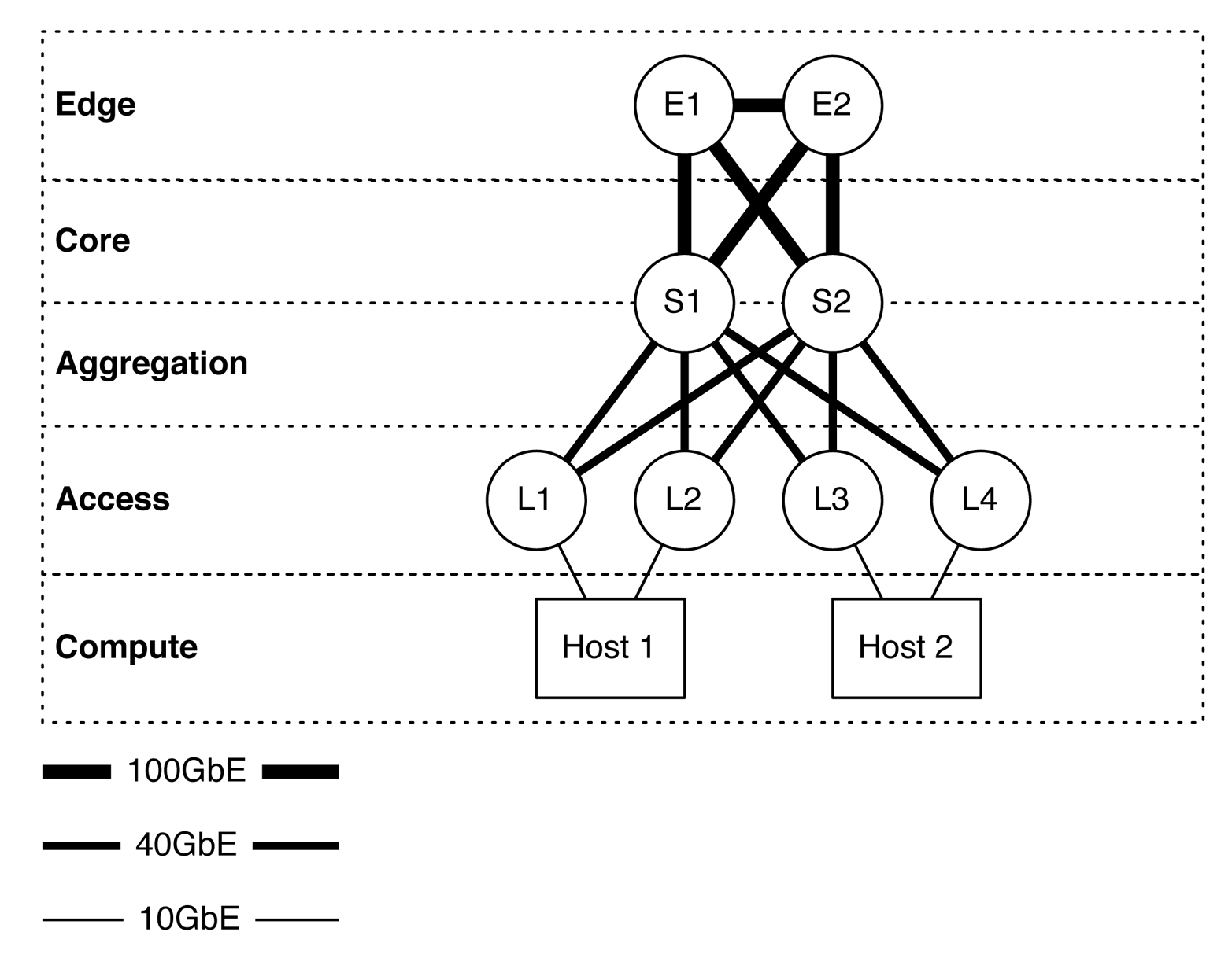
Figure 1-9. The Juniper QFX10002-36Q in multiple tiers in a spine-and-leaf architecture
Attributes
Table 1-2 takes a closer look at the most common attributes of the Juniper QFX10002-36Q. You can use it to quickly find physical and environmental information.
| Attribute | Value |
|---|---|
| Rack units | 2 |
| System throughput | 2.88Tbps |
| Forwarding capacity | 1 Bpps |
| Built-in interfaces | 36xQSFP+ |
| Total 10GbE interfaces | 144x10GbE |
| Total 40GbE interfaces | 36x40GbE |
| Total 100GbE interfaces | 12x100GbE |
| Airflow | Airflow In (AFI) or Airflow Out (AFO) |
| Typical power draw | 560 W |
| Maximum power draw | 800 W |
| Cooling | 3 fans with N + 1 redundancy |
| Total packet buffer | 12 GB |
| Latency | 2.5 μs within PFE or 5.5 μs across PFEs |
The Juniper QFX10002-36Q packs an amazing amount of bandwidth and port density in a very small 2RU form factor. As denoted by the model number, the Juniper QFX10002-36Q has 32 built-in 40GbE interfaces that you can break out into 4x10GbE each, or you can turn groups of three into a single 100GbE interface, as demonstrated in Figure 1-10.

Figure 1-10. Juniper QFX10002-36Q port groups
Each port group consists of three ports. For example, ports 0, 1, and 2 are in a port group; ports 3, 4, and 5 are in a separate port group. Port groups play a critical role on how the tri-speed interfaces can operate. The rules are as follows:
- 10GbE interfaces
- If you decide to break out a 40GbE interface into 4x10GbE interfaces, it must apply to the entire port group. The configuration must be applied only to the first interface of the port group. For example, to break out interface et-0/0/1 into 4x10GbE, you first must identify what port group it belongs to, which in this case is the first port group. The next step is to determine which other interfaces are part of this port group; in our case, it’s et-0/0/0, et-0/0/1, and et-0/0/2. To break out interface et-0/0/1, you need to set the configuration of interface et-0/0/0 to support channelized interfaces. The reason for this is that interface et-0/0/0 is the first interface in the port group to which et-0/0/1 belongs. In summary, all interfaces within that port group will be broken out into 4x10GbE interfaces. That means you must break out et-0/0/0, et-0/0/1, and et-0/0/2 into 4x10GbE interfaces.
- 40GbE interfaces
- By default, all ports are 40GbE. No special rules here.
- 100GbE interfaces
- Only a single interface within a port group can be turned into 100GbE. If you enable 100GbE within a port group, the other two ports within the same port group are disabled and cannot be used. Figure 1-10 illustrates which ports within a port group are 100GbE-capable by showing the interface name in bold. For example, the interface 1 in the first port group supports 100GbE, whereas interfaces 0 and 2 are disabled. In the second port group, interface 5 supports 100GbE, whereas interfaces 3 and 4 are disabled.
You configure tri-speed interface settings on a per–port group basis. For example, port group 1 might support 12x10GbE and port group 2 might support a single 1x100GbE interface. Overall, the system is very flexible in terms of tri-speed configurations.
Management panel
The Juniper QFX10002-36 is split into two functional areas (Figure 1-11): the port panels and management panel.
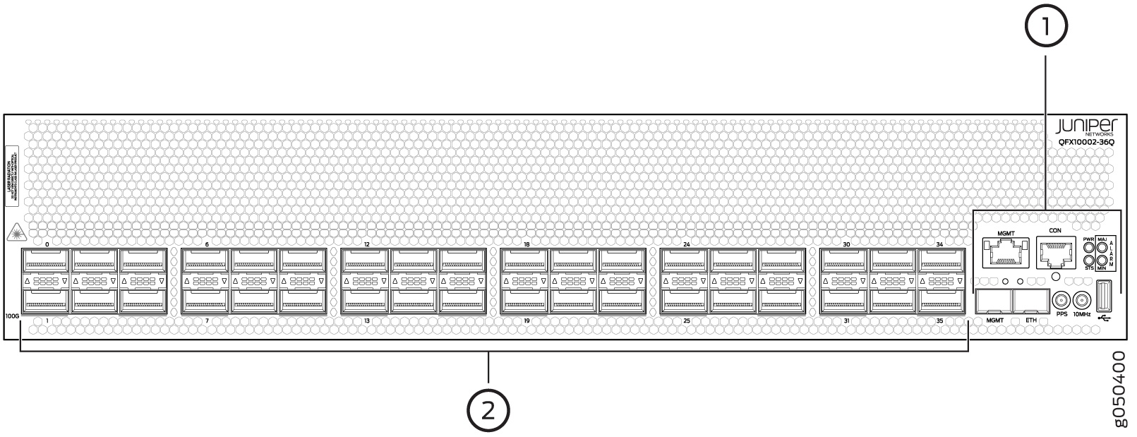
Figure 1-11. Juniper QFX10002-36Q management panel (1) and port panel (2)
Figure 1-12 presents an enlarged view of the management panel.
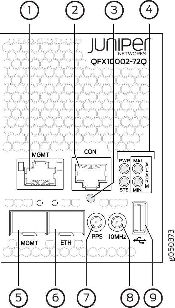
Figure 1-12. Juniper QFX10002 management panel components
The management panel is full of the usual suspects to physically manage the switch and provide external storage. Let’s go through them one by one:
-
em0-RJ-45 (1000BASE-T) management Ethernet port (MGT).
-
RJ-45 console port (CON) that supports RS-232 serial connections.
-
Reset button. To reset the entire switch except the clock and FPGA functions, press and hold this button for five seconds.
-
Status LEDs.
-
em1-SFP management Ethernet port (MGT).
-
PTP Ethernet-SFP (1000BASE-T) port (ETH).
-
10 Hz pulses-per-second (PPS) Subminiature B (SMB) connector for input and output measuring the time draft from an external grandmaster clock.
-
10 MHz SMB timing connector.
-
USB port for external storage and other devices.
There are two management ports on a QFX10002 that have LEDs whose purpose is to indicate link status and link activity (see Figure 1-13). These two ports, located on the management panel next to the access ports, are both labeled MGMT. The top management port is for 10/100/1000 BASE-T connections and the lower port is for 10/100/1000 BASE-T and small-form pluggable (SFP) 1000 BASE-X connections. The copper RJ45 port has separate LEDs for status and activity. The fiber SFP port has a combination link and activity LED.
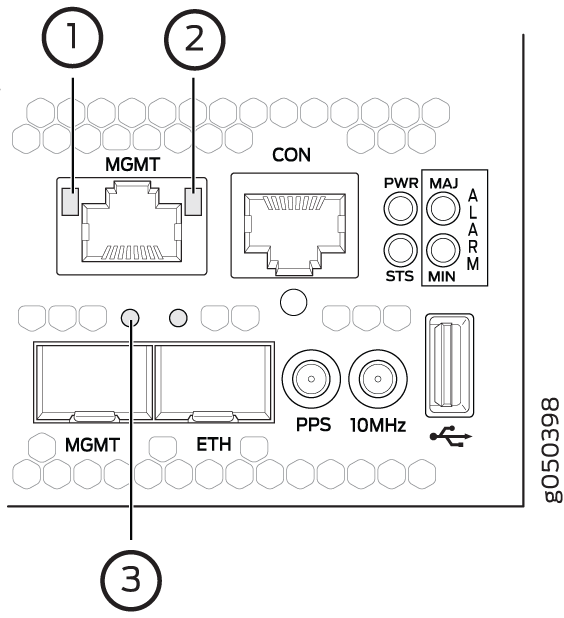
Figure 1-13. Juniper QFX10002 management port LEDs
Table 1-3 list the LED status representations.
| LED | Color | State | Description |
|---|---|---|---|
| Link/activity | Off | Off | No link established, fault, or link is down. |
| Yellow | Blinking | Link established with activity. | |
| Status | Off | Off | Port speed is 10M or link is down. |
| Green | On | Port speed is 1000M. |
Figure 1-14 shows additional chassis status LEDs on the right side of the switch indicate the overall health of the switch; this includes faults, power, and general status.

Figure 1-14. Juniper QFX10002 chassis status LEDs
Table 1-4 lists what the chassis status LEDs indicate.
| Name | Color | State | Description |
|---|---|---|---|
| PWR-Alarm | Off | Off | Powered off |
| Green | On | Powered on | |
| Yellow | Blinking | Power fault | |
| STA-Status | Off | Off | Halted or powered off |
| Green | On | Junos loaded | |
| Green | Blinking | Beacon active | |
| Yellow | Blinking | Fault | |
| MJR-Major alarm | Off | Off | No alarms |
| Red | On | Major alarm | |
| MIN-Minor alarm | Off | Off | No alarms |
| Yellow | On | Minor alarm |
FRU Panel
Figure 1-15 shows the rear of the QFX10002, where you will find the Field Replaceable Units (FRUs) for power and cooling.

Figure 1-15. Juniper QFX10002-36Q FRU panel
Let’s inspect each element in more detail:
-
AC or DC power supplies. The QFX10002-36Q has two power supplies. The QFX10002-72Q has four power supplies.
-
Reversible fans. Supports AFI and AFO.
-
Electrostatic discharge (ESD) connector.
Walk around the Juniper QFX10002
Let’s take a quick tour of the Juniper QFX10002. We just went through all of the status LEDs, alarms, management ports, and FRUs. Now let’s see them in action from the command line.
To see if there are any chassis alarms, use the following command:
dhanks@qfx10000-02> show chassis alarms
2 alarms currently active
Alarm time               Class  Description
2016-01-11 00:07:28 PST  Major  PEM 3 Not Powered
2016-01-11 00:07:28 PST  Major  PEM 2 Not Powered
To see the overall operating environment, use the show chassis environment command, as demonstrated here:
dhanks@qfx10000-02> show chassis environment
Class Item                           Status     Measurement
Power FPC 0 Power Supply 0           OK
      FPC 0 Power Supply 1           OK
      FPC 0 Power Supply 2           Present
      FPC 0 Power Supply 3           Present
Temp  FPC 0 Intake Temp Sensor       OK         20 degrees C / 68 degrees F
      FPC 0 Exhaust Temp Sensor      OK         28 degrees C / 82 degrees F
      FPC 0 Mezz Temp Sensor 0       OK         20 degrees C / 68 degrees F
      FPC 0 Mezz Temp Sensor 1       OK         31 degrees C / 87 degrees F
      FPC 0 PE2 Temp Sensor          OK         26 degrees C / 78 degrees F
      FPC 0 PE1 Temp Sensor          OK         26 degrees C / 78 degrees F
      FPC 0 PF0 Temp Sensor          OK         34 degrees C / 93 degrees F
      FPC 0 PE0 Temp Sensor          OK         26 degrees C / 78 degrees F
      FPC 0 PE5 Temp Sensor          OK         27 degrees C / 80 degrees F
      FPC 0 PE4 Temp Sensor          OK         27 degrees C / 80 degrees F
      FPC 0 PF1 Temp Sensor          OK         39 degrees C / 102 degrees F
      FPC 0 PE3 Temp Sensor          OK         27 degrees C / 80 degrees F
      FPC 0 CPU Die Temp Sensor      OK         30 degrees C / 86 degrees F
      FPC 0 OCXO Temp Sensor         OK         32 degrees C / 89 degrees F
Fans  FPC 0 Fan Tray 0 Fan 0         OK         Spinning at normal speed
      FPC 0 Fan Tray 0 Fan 1         OK         Spinning at normal speed
      FPC 0 Fan Tray 1 Fan 0         OK         Spinning at normal speed
      FPC 0 Fan Tray 1 Fan 1         OK         Spinning at normal speed
      FPC 0 Fan Tray 2 Fan 0         OK         Spinning at normal speed
      FPC 0 Fan Tray 2 Fan 1         OK         Spinning at normal speed
Using the show chassis environment, you can quickly get a summary of the power, temperatures, and fan speeds of the switch. In the preceding example, everything is operating correctly.
For more detail on the power supplies, use the following command:
dhanks@qfx10000-02> show chassis environment fpc pem
fpc0:
--------------------------------------------------------------------------
FPC 0 PEM 0 status:
  State                      Online
  Temp Sensor 0              OK   22 degrees C / 71 degrees F
  Temp Sensor 1              OK   32 degrees C / 89 degrees F
  Temp Sensor 2              OK   34 degrees C / 93 degrees F
  Fan 0                      5096 RPM
  Fan 1                      6176 RPM
  DC Output           Voltage(V) Current(A)  Power(W)  Load(%)
                          12        30            360      55
FPC 0 PEM 1 status:
  State                      Online
  Temp Sensor 0              OK   24 degrees C / 75 degrees F
  Temp Sensor 1              OK   34 degrees C / 93 degrees F
  Temp Sensor 2              OK   34 degrees C / 93 degrees F
  Fan 0                      4800 RPM
  Fan 1                      5760 RPM
  DC Output           Voltage(V) Current(A)  Power(W)  Load(%)
Now, let’s get more information about the chassis fans:
dhanks@qfx10000-02> show chassis fan
      Item                      Status   RPM     Measurement
      FPC 0 Tray 0 Fan 0        OK       5000    Spinning at normal speed
      FPC 0 Tray 0 Fan 1        OK       4400    Spinning at normal speed
      FPC 0 Tray 1 Fan 0        OK       5500    Spinning at normal speed
      FPC 0 Tray 1 Fan 1        OK       4400    Spinning at normal speed
      FPC 0 Tray 2 Fan 0        OK       5000    Spinning at normal speed
      FPC 0 Tray 2 Fan 1        OK       4400    Spinning at normal speed
Next, let’s see what the routing engine in the Juniper QFX10002 is doing:
dhanks@qfx10000-02> show chassis routing-engine
Routing Engine status:
  Slot 0:
    Current state                  Master
    Temperature                 20 degrees C / 68 degrees F
    CPU temperature             20 degrees C / 68 degrees F
    DRAM                      3360 MB (4096 MB installed)
    Memory utilization          19 percent
    5 sec CPU utilization:
      User                      12 percent
      Background                 0 percent
      Kernel                     1 percent
      Interrupt                  0 percent
      Idle                      88 percent
    1 min CPU utilization:
      User                      10 percent
      Background                 0 percent
      Kernel                     1 percent
      Interrupt                  0 percent
      Idle                      90 percent
    5 min CPU utilization:
      User                       9 percent
      Background                 0 percent
      Kernel                     1 percent
      Interrupt                  0 percent
      Idle                      90 percent
    15 min CPU utilization:
      User                       9 percent
      Background                 0 percent
      Kernel                     1 percent
      Interrupt                  0 percent
      Idle                      90 percent
    Model                          RE-QFX10002-72Q
    Serial ID                      BUILTIN
    Uptime                         5 days, 10 hours, 29 minutes, 29 seconds

    Last reboot reason             0x2000:hypervisor reboot
    Load averages:                 1 minute   5 minute  15 minute
                                       0.08       0.03       0.01
Finally, let’s get detailed temperature information about all of the PFEs and fabric chips in the chassis:
dhanks@qfx10000-02> show chassis sibs temperature-thresholds
                           Fan speed      Yellow alarm      Red alarm   Fire Shutdown
                          (degrees C)      (degrees C)     (degrees C)   (degrees C)
Item                     Normal  High   Normal  Bad fan   Normal  Bad fan    Normal
FPC 0 Intake Temp Sensor     30    65       65       65       70       70      75
FPC 0 Exhaust Temp Sensor    30    65       65       65       70       70      75
FPC 0 Mezz Temp Sensor 0     30    65       65       65       70       70      75
FPC 0 Mezz Temp Sensor 1     30    65       65       65       70       70      75
FPC 0 PE2 Temp Sensor        50    90       90       90      100      100     103
FPC 0 PE1 Temp Sensor        50    90       90       90      100      100     103
FPC 0 PF0 Temp Sensor        50    90       90       90      100      100     103
FPC 0 PE0 Temp Sensor        50    90       90       90      100      100     103
FPC 0 PE5 Temp Sensor        50    90       90       90      100      100     103
FPC 0 PE4 Temp Sensor        50    90       90       90      100      100     103
FPC 0 PF1 Temp Sensor        50    90       90       90      100      100     103
FPC 0 PE3 Temp Sensor        50    90       90       90      100      100     103
FPC 0 CPU Die Temp Sensor    50    90       90       90      100      100     103
FPC 0 OCXO Temp Sensor       50    90       90       90      100      100     103
Juniper QFX10002-72Q
Figure 1-16 shows the Juniper QFX10002-72Q, the workhouse of the fixed-switches. It’s filled to the brim with 72x40GbE interfaces with deep buffers, high logical scale, and tons of features.

Figure 1-16. Juniper QFX10002-72Q switch
Again, the Juniper Q5 chipset powers the Juniper QFX10002-72Q, just like its little brother, the Juniper QFX10002-36Q. Let’s take a quick look at the port options of the Juniper QFX10002-72Q:
-
72x40GbE (QSFP28)
-
24x100GbE (QSFP28)
-
288x10GbE (SFP+)
Right out of the box, the Juniper QFX10002-72Q offers tri-speed ports: 10GbE, 40GbE, and 100GbE. The 10GbE ports require that you use a break-out cable, which results in 4x10GbE ports for every 40GbE port. However, to support a higher speed port, you must combine 3 40GbE ports together to support a single 100GbE port. This means that two adjacent 40GbE ports will be disabled to support a 100GbE port.
Role
The Juniper QFX10002-72Q is designed primarily as a spine switch to operate in the aggregation and core of the network, as shown in Figure 1-17.

Figure 1-17. Juniper QFX10002-72S as a spine switch in network topology
In the figure, “S” refers to the spine switch, and “L” refers to the leaf switch (spine-and-leaf topology). We have taken a traditional, tiered data center model with core, aggregation, and access and superimposed the new spine and leaf topology.
The Juniper QFX10002-72Q has enough bandwidth and port density, in a small to medium-sized environment, to collapse both the traditional core and aggregation functions. For example, a single pair of Juniper QFX10002-72Q switches using Juniper QFX5100-48S as leaf switches results in 3,456x10GbE interfaces with only 6:1 over-subscription. Again, you can adjust these calculations up or down based on the over-subscription and port densities required for your environment.
Expanding the example, Figure 1-18 illustrates how the edge routers and servers connect into the spine-and-leaf architecture. The Juniper QFX10002-72Q is shown as S1 and S2, whereas Juniper QFX5100 switches are shown as L1 through L4. The connections between the spine and leaf are 40GbE, whereas the connections from the spine to the edge are 100GbE. In the case of the edge tier, the assumption is that these devices are Juniper MX routers. Finally, the hosts connect into the leaf switches by using 10GbE.
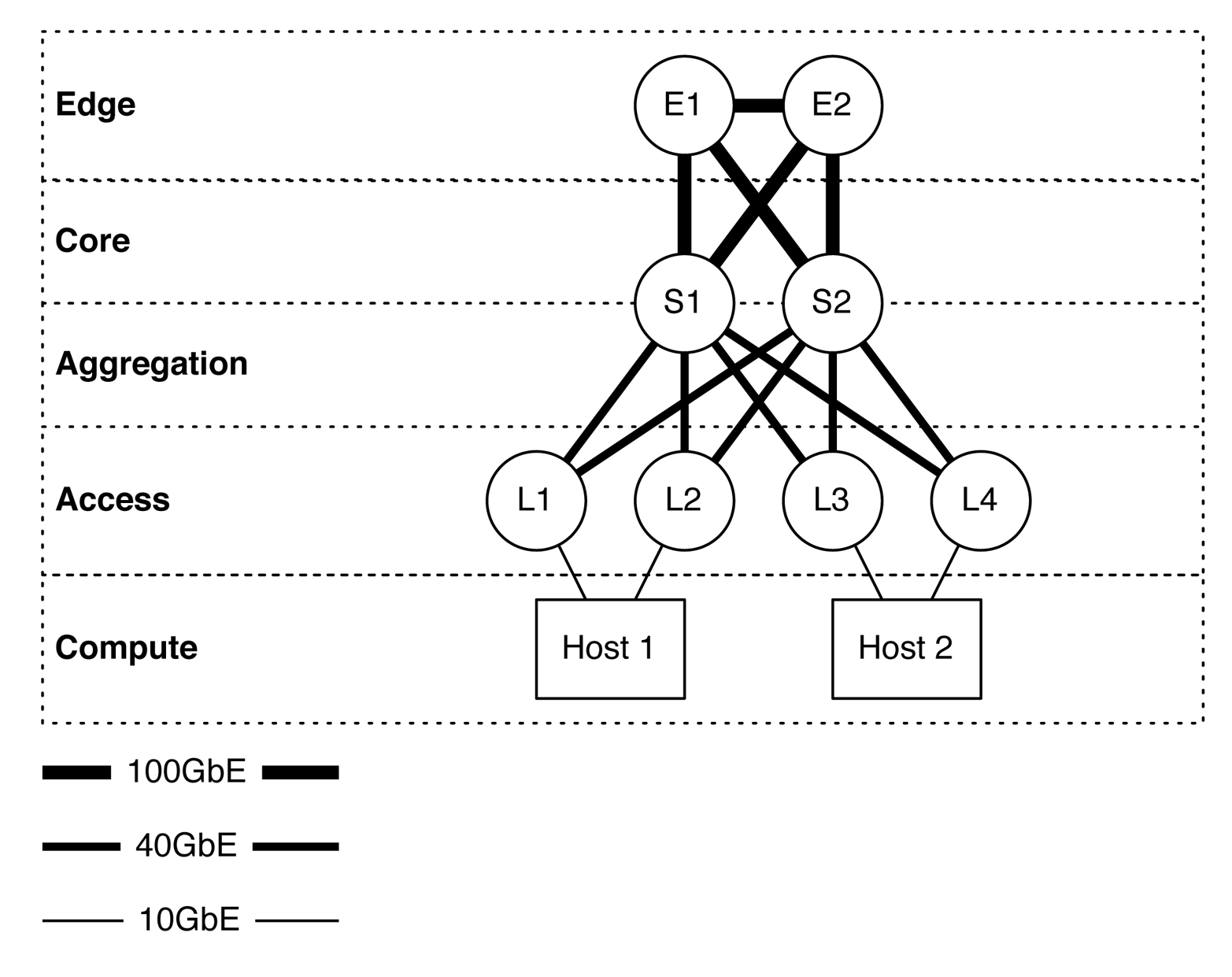
Figure 1-18. The Juniper QFX10002-72Q in multiple tiers in a spine-and-leaf architecture
Attributes
Let’s take a closer look at the most common attributes of the Juniper QFX10002-72Q, which are presented in Table 1-5.
| Attribute | Value |
|---|---|
| Rack units | 2 |
| System throughput | 5.76Tbps |
| Forwarding capacity | 2 Bpps |
| Built-in interfaces | 72xQSFP+ |
| Total 10GbE interfaces | 288x10GbE |
| Total 40GbE interfaces | 72x40GbE |
| Total 100GbE interfaces | 24x100GbE |
| Airflow | AFI or AFO |
| Typical power draw | 1,050 W |
| Maximum power draw | 1,450 W |
| Cooling | 3 fans with N + 1 redundancy |
| Total packet buffer | 24 GB |
| Latency | 2.5 μs within PFE or 5.5 μs across PFEs |
The Juniper QFX10002-72Q packs an amazing amount of bandwidth and port density in a very small 2RU form factor. As denoted by the model number, the Juniper QFX10002-72Q has 72 built-in 40GbE interfaces, which you can break out into 4x10GbE each or you can turn groups of three into a single 100GbE interface, as depicted in Figure 1-19.

Figure 1-19. Juniper QFX10002-72Q port groups
Each port group consists of three ports. For example, ports 0, 1, and 2 are in a port group; ports 3, 4, and 5 are in a separate port group. Port groups play a critical role in how the tri-speed interfaces can operate. The rules are as follows:
- 10GbE interfaces
- If you decide to break out a 40GbE interface into 4x10GbE interfaces, it must apply to the entire port group. The configuration must be applied only to the first interface of the port group. For example, to break out interface et-0/0/1 into 4x10GbE, you first must identify to which port group it belongs; in this case, it is the first port group. The next step is to determine which other interfaces are part of this port group; in our case, it’s et-0/0/0, et-0/0/1, and et-0/0/2. To break out interface et-0/0/1, you need to set the configuration of interface et-0/0/0 to support channelized interfaces. The reason for this is because interface et-0/0/0 is the first interface in the port group to which et-0/0/1 belongs. In summary, all interfaces within that port group will be broken out into 4x10GbE interfaces. This means that you must break out et-0/0/0, et-0/0/1, and et-0/0/2 into 4x10GbE interfaces.
- 40GbE interfaces
- By default, all ports are 40GbE. No special rules here.
- 100GbE interfaces
- Only a single interface within a port group can be turned into 100GbE. If you enable 100GbE within a port group, the other two ports within the same port group are disabled and cannot be used. Figure 1-19 illustrates which ports within a port group are 100GbE-capable by showing the interface name in bold. For example, the interface 1 in the first port group supports 100GbE, whereas interfaces 0 and 2 are disabled. The second port group, interface 5 supports 100GbE, whereas interfaces 3 and 4 are disabled.
You configure tri-speed interface settings on a per–port group basis. For example, port group 1 might support 12x10GbE and port group 2 might support a single 100GbE interface. Overall, the system is very flexible in terms of tri-speed configurations.
Management/FRU panels
The management and FRU panels of the Juniper QFX10002-72Q are identical to the Juniper QFX10002-36Q, so there’s no need to go over the same information. Feel free to refer back to “Juniper QFX10002-72Q” for detailed information about the management and FRU panels.
Juniper QFX10008
The Juniper QFX10008 (Figure 1-20) is the smallest modular chassis switch in the Juniper QFX10000 Series. This chassis has eight slots for line cards and two slots for redundant routing engines. In the figure, the following line cards are installed, ordered top to bottom:
-
QFX10000-36Q
-
QFX10000-36Q
-
QFX10000-36Q
-
QFX10000-36Q
-
QFX10000-36Q
-
QFX10000-60S-6Q
-
QFX10000-30C
-
QFX10000-30C
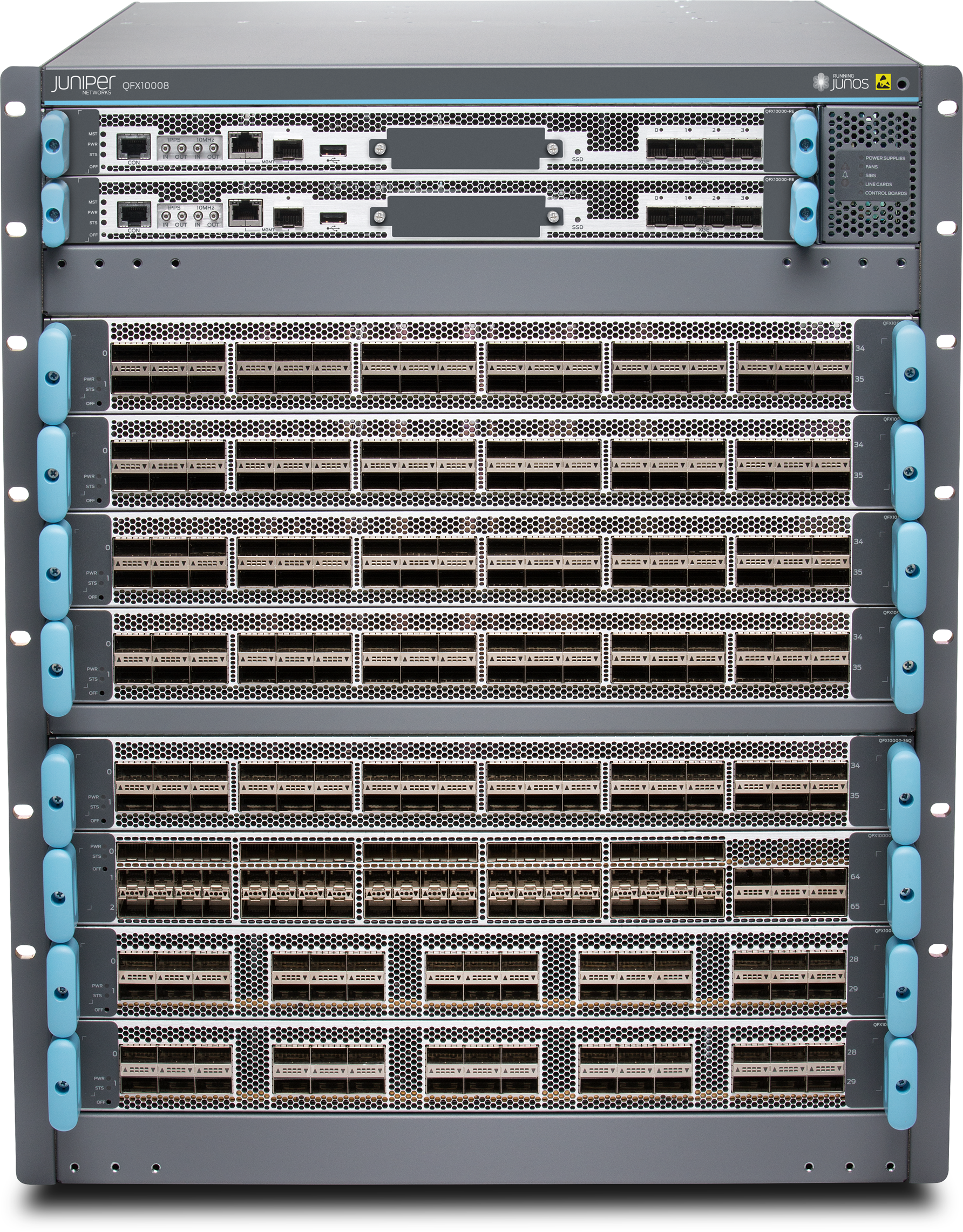
Figure 1-20. The Juniper QFX10008 chassis switch
As always, the Juniper Q5 chipset powers the Juniper QFX10008 (likewise its little brother, the Juniper QFX10002). The only difference between the QFX10002 and QFX10008 is that the QFX10008 is modular and supports line cards and two physical routing engines. Otherwise, the features, scale, and buffer are the same. Some of the line cards have small differences in buffer speed, but we’ll discuss that later in the chapter. In summary, the Juniper QFX10008 offers the same features, scale, and performance as the QFX10002, except it offers more ports due to its larger size and line-card options.
Role
The Juniper QFX10008 is designed as a spine switch to operate in the aggregation and core of the network, as shown in Figure 1-21.

Figure 1-21. Juniper QFX10008 as a spine switch in a network topology
In Figure 1-21, the “S” refers to the spine switch, and the “L” refers to the leaf switch (spine-and-leaf topology). We have taken a traditional, tiered data center model with core, aggregation, and access and superimposed the new spine-and-leaf topology.
The Juniper QFX10008 has enough bandwidth and port density, in a medium to large-sized environment, to collapse both the traditional core and aggregation functions. For example, a single pair of Juniper QFX10008 switches using Juniper QFX5100-48S as leaf switches results in 13,824 10GbE interfaces with only 6:1 over-subscription. You can adjust these calculations up or down based on the over-subscription and port densities required for your environment.
Expanding the example, Figure 1-22 illustrates how the edge routers and servers connect into the spine-and-leaf architecture. The Juniper QFX10008 is shown as S1 and S2, whereas Juniper QFX5100 switches are shown as L1 through L4. The connections between the spine and leaf are 40GbE, whereas the connections from the spine to the edge are 100GbE. In the case of the edge tier, the assumption is that these devices are Juniper MX routers. Finally, the hosts connect into the leaf switches by using 10GbE.
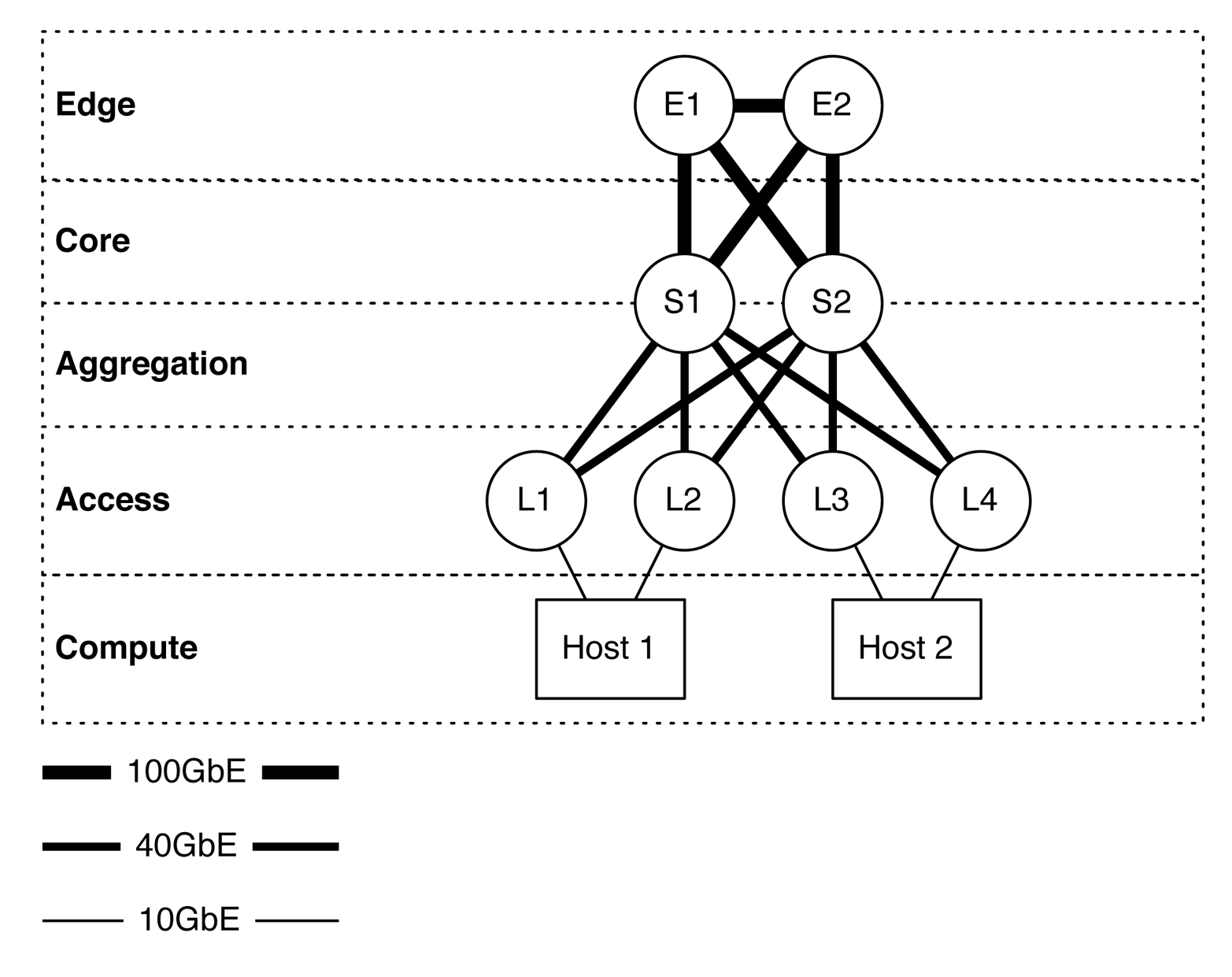
Figure 1-22. The Juniper QFX10008 in multiple tiers in a spine-and-leaf architecture
Attributes
Table 1-6 lists the most common attributes of the Juniper QFX10008.
| Attribute | Value |
|---|---|
| Rack units | 13 |
| Fabric capacity | 96Tbps (system) and 7.2Tbps (slot) |
| Forwarding capacity | 16 Bpps |
| Line card capacity | 8 |
| Routing engine capacity | 2 |
| Switching fabrics | 6 |
| Maximum 10GbE interfaces | 1,152x10GbE |
| Maximum 40GbE interfaces | 288x40GbE |
| Maximum 100GbE interfaces | 240x100GbE |
| Airflow | Front-to-back |
| Typical power draw | 1,659 W (base) and 2,003 W (redundant) |
| Reserved power | 2,517 W (base) and 2,960 W (redundant) |
| Cooling | 2 fan trays with 1 + 1 redundancy |
| Maximum packet buffer | 96 GB |
| Latency | 2.5 μs within PFE or 5.5 μs across PFEs |
The Juniper QFX10008 is a very flexible chassis switch that’s able to fit into smaller data centers and provide high logical scale, deep buffers, and tons of features.
Juniper QFX10016
The Juniper QFX10016 (Figure 1-23) is the largest spine switch that Juniper offers in the QFX10000 Series. It’s an absolute monster weighting in at 844 lbs fully loaded and able to provide 288Tbps of fabric bandwidth at 32 Bpps.
There are not a lot of differences between the Juniper QFX10008 and QFX10016 apart from the physical scale. Thus, we’ll make this section very short and highlight only the differences. Table 1-7 lists the most common attributes of the QFX10016.
| Attribute | Value |
|---|---|
| Rack units | 21 |
| Fabric capacity | 288Tbps (system) and 7.2Tbps (slot) |
| Forwarding capacity | 16 Bpps |
| Line card capacity | 16 |
| Routing engine capacity | 2 |
| Switching fabrics | 6 |
| Maximum 10GbE interfaces | 2,304x10GbE |
| Maximum 40GbE interfaces | 576x40GbE |
| Maximum 100GbE interfaces | 480x100GbE |
| Airflow | Front-to-back |
| Typical power draw | 4,232 W (base) and 4,978 W (redundant) |
| Reserved power | 6,158 W (base) and 7,104 W (redundant) |
| Cooling | 2 fan trays with 1 + 1 redundancy |
| Maximum packet buffer | 192 GB |
| Latency | 2.5 μs within PFE or 5.5 μs across PFEs |
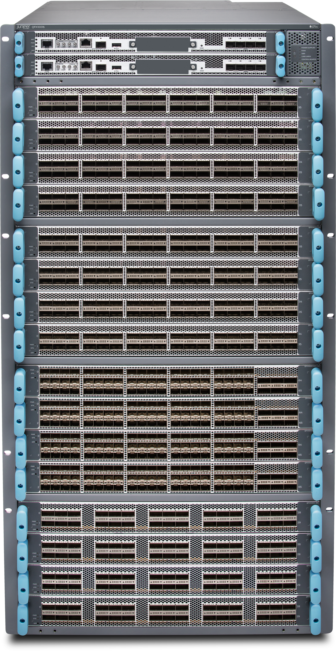
Figure 1-23. Juniper QFX10016 chassis switch
The Juniper QFX10008 shares the same line cards, power supplies, and routing engines/control boards with the larger Juniper QFX10016. The fan trays and switch fabric are different between the two Juniper QFX10000 chassis because of the physical height differences.
Juniper QFX10K Line Cards
As of this writing, there are three line cards for the Juniper QFX10000 chassis: QFX10000-36Q, QFX10000-30C, and the QFX10000-60S-6Q. Each line card is full line-rate and non-blocking. Also, each line card offers high logical scale with deep buffers.
Juniper QFX10000-36Q
The first line card has 36-port 40GbE interfaces, which is similar to the QFX10002-36Q, but in a line card form factor. The QFX10000-36Q line card (Figure 1-24) also supports 100GbE interfaces using port groups; we use the same method of disabling two out of three interfaces per port group. The QFX10000-36Q supports the following interface configurations:
-
144x10GbE interfaces
-
36x40GbE interfaces
-
12x100GbE interfaces
-
Or any combination of per–port group configurations

Figure 1-24. The Juniper QFX10000-36Q line card
The QFX10000-36Q has three PFEs that provide enough bandwidth, buffer, and high scale for all 36x40GbE interfaces, as shown in Figure 1-25.
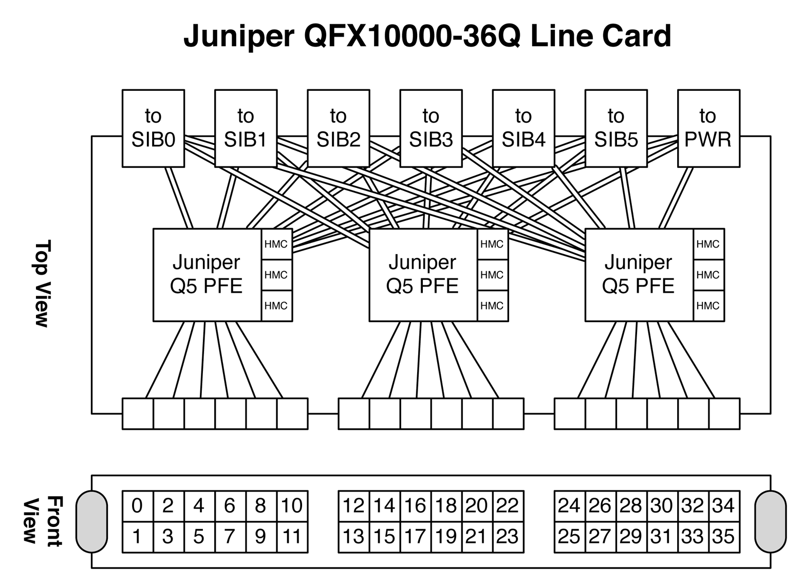
Figure 1-25. Juniper QFX10000-36Q architecture
Each of the PFEs have three 2 GB Hybrid Memory Cubes (HMCs), so each Juniper Q5 chip has a total 6 GB of memory. 2 GB of memory is allocated for hardware tables (FIB, etc.) and 4 GB is allocated for packet buffer. Each PFE handles a set of interfaces; in the case of the Juniper Q5 chip, it can handle 48x10GbE, 12x40GbE, or 5x100GbE ports. The QFX10000-36Q line card has 36x40GbE interfaces, so each Juniper Q5 chip is assigned to three groups of 12 interfaces, as shown in Figure 1-25. Each Juniper Q5 chip is connected in a full mesh to every single Switch Interface Board (SIB). Having a connection to each SIB ensures that the PFE is able to transmit traffic during any SIB failure in the system. There are actually many different connections from each PFE to a single SIB, but we’ll discuss the SIB architecture in the next section. Each Juniper Q5 chip is connected to every other Juniper Q5 chip in the system; so regardless of the traffic profiles in the switch, everything is a single hop away.
Juniper QFX10000-30C
The next line card in the family is the QFX10000-30C, as shown in Figure 1-26. This is a native 30x100GbE QSFP28 line card, but also supports 30x40GbE in a QSFP+ form factor.

Figure 1-26. Juniper QFX10000-30C line card
Because of the large number of 100GbE interfaces, each QFX10000-C line card requires a total of six Juniper Q5 chips, as illustrated in Figure 1-27. If you recall, each Juniper Q5 chip can handle up to 5x100GbE interfaces. The double-lines in the figure represent the Q5-to-SIB connection, whereas the single lines represent an interface-to-Q5 connection.
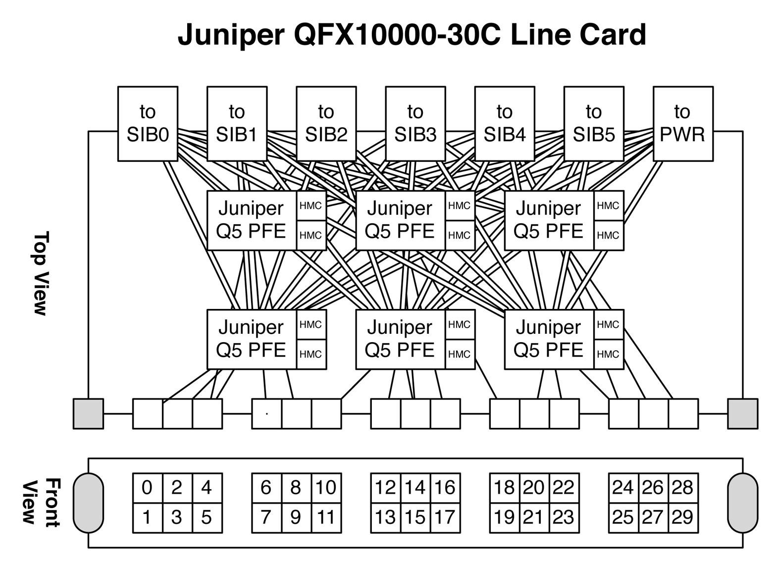
Figure 1-27. Juniper QFX1000-30C architectureJuniper QFX10000-60S-6Q
The third line card is the QFX10000-60S-6Q (Figure 1-28), which supports 60x10GbE and 6x40GbE. You can also enable 2x100GbE interfaces by disabling two out of the three interfaces per port group.

Figure 1-28. Juniper QFX10000-60S-6Q line card
A single Juniper Q5 chip is used to handle the first 48x10GbE ports; a second Juniper Q5 chip is used to handle the remaining 12x10GbE and 6x40GbE interfaces, as depicted in Figure 1-29. Each Juniper Q5 chip is connected to every SIB in a full mesh just like all of the other Juniper QFX10000 line cards.
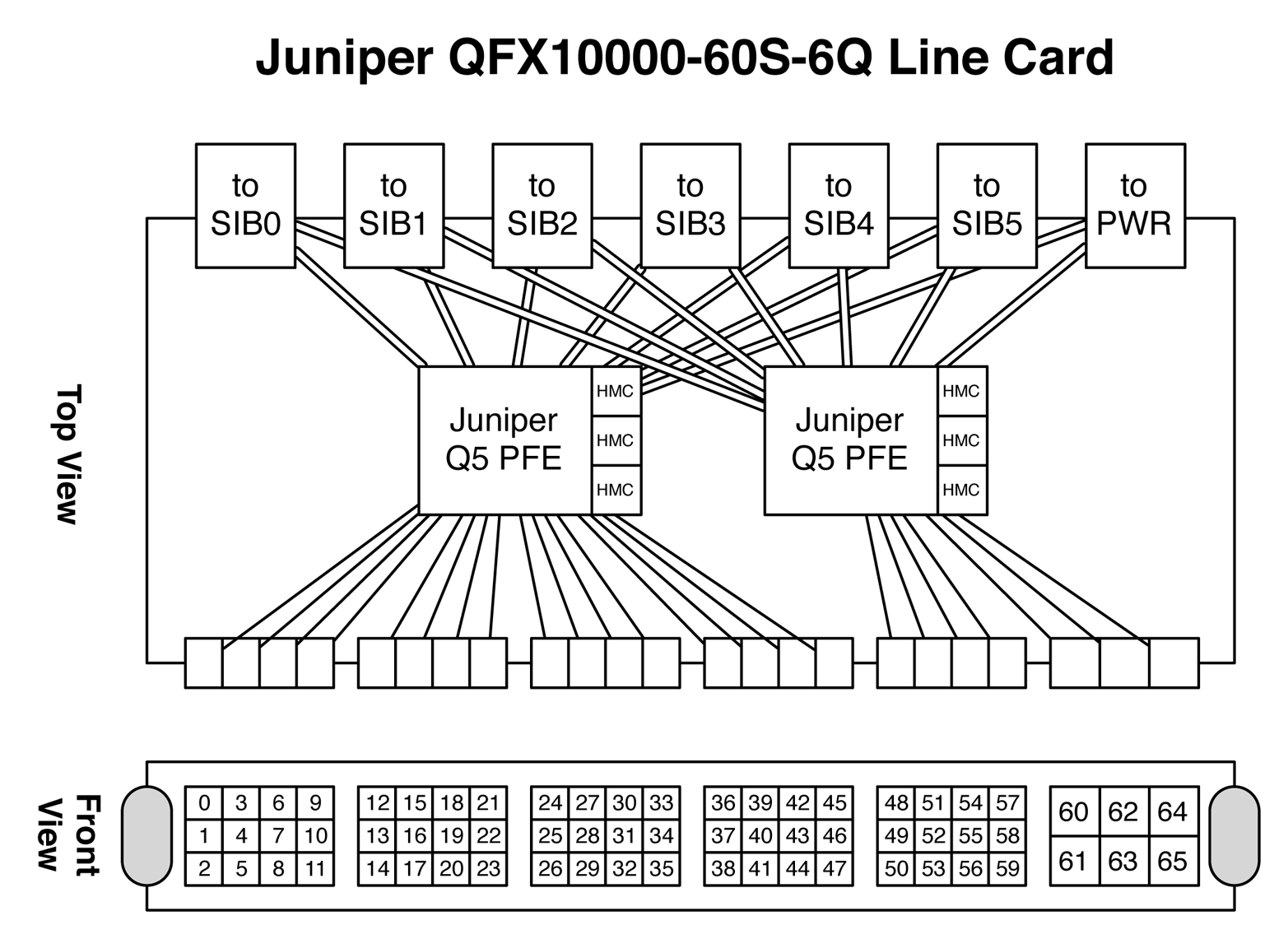
Figure 1-29. Juniper QFX10000-60S-6Q architecture
QFX10000 Control Board
The QFX10000 routing engine is basically a modern server. It has the latest Intel Ivy Bridge processor, SSD, and DDR3 memory. The routing engine provides the standard status LEDs, management interfaces, precision-timing interfaces, USB support, and built-in network cards, as shown in Figure 1-30.

Figure 1-30. Juniper QFX10000 routing engine
Here are the specifications of the Juniper QFX10000 routing engine:
-
Intel Ivy Bridge 4-core 2.5 GHz Xeon Processor
-
32 GB DDR3 SDRAM—four 8 GB DIMMs
-
50 GB internal SSD storage
-
One 2.5-inch external SSD slot
-
Internal 10 GB NICs for connectivity to all line cards
-
RS232 console port
-
RJ-45 and SFP management Ethernet
-
Precision-time protocol logic and SMB connectors
-
4x10GbE management ports
The routing engines also have hardware-based arbitration built in for controlling the line cards and SIBs. If the master routing engine fails over to the backup, the event is signaled in hardware so that all of the other chassis components have a fast and clean cutover to the new master routing engine.
SIBs
The SIBs are the glue that interconnect every single line card and PFE together in the chassis. Every PFE is only a single hop away from any other PE in the system. The Juniper QFX10008 and QFX10016 have a total six SIBs each; this provides 5 + 1 redundancy. If any single SIB were to fail, the other five SIBs can provide line-rate switching between all the PFEs. If additional SIBs were to fail, the system would gracefully fail and only reduce the overall bandwidth between line cards. Because of the physical height difference between the Juniper QFX10008 and QFX10016 chassis, they use different SIBs and cannot be shared between the chassis.
Request and grant
Every time a PFE wants to speak to another PFE, it must go through a request-and-grant system. This process lets the ingress PFE reserve a specific amount of bandwidth to an egress PFE, port, and forwarding class, as illustrated in Figure 1-31. The request and grant process is handled completely in hardware end-to-end to ensure full line-rate performance.
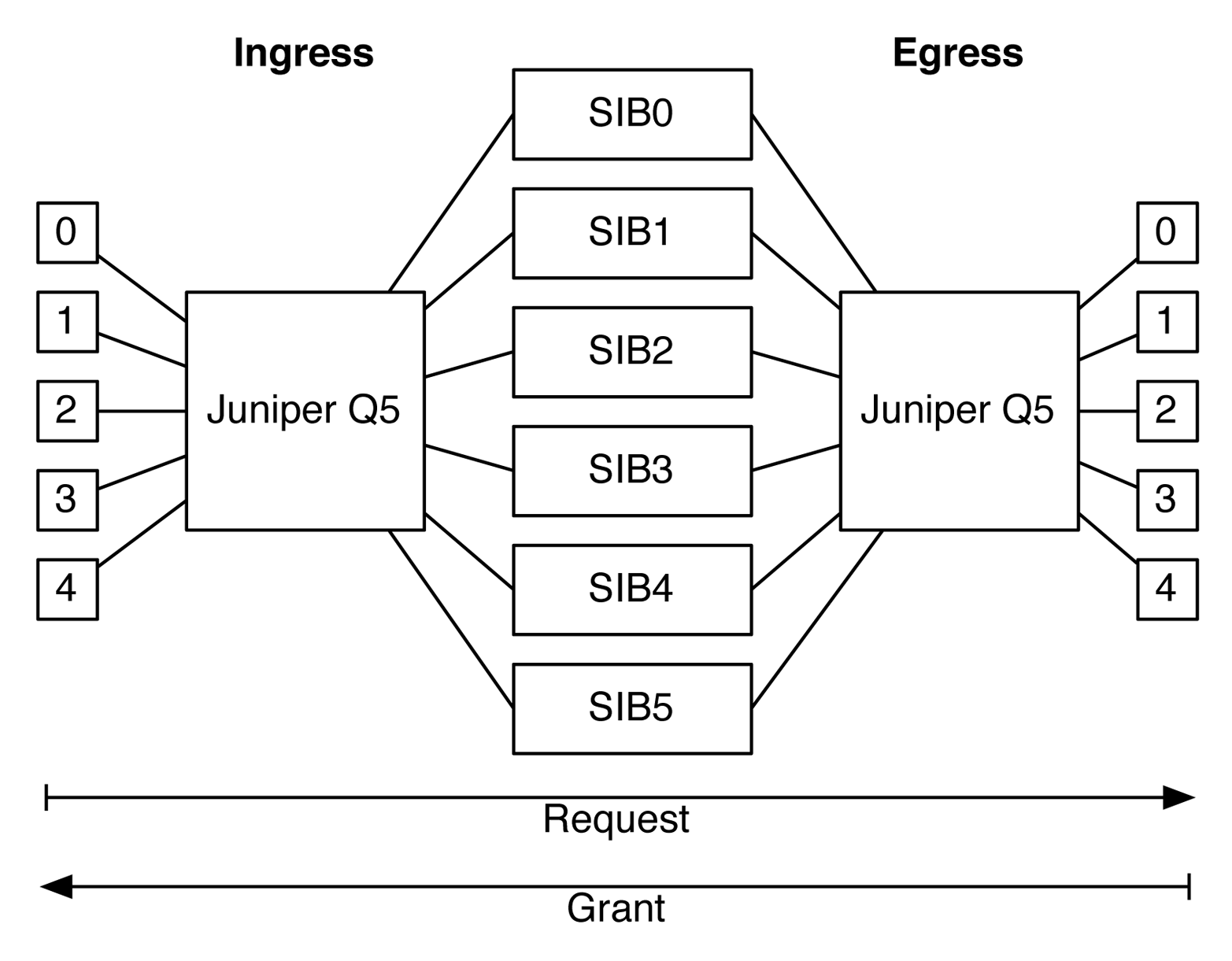
Figure 1-31. Juniper request-and-grant architecture
In the figure, the boxes labeled 0 through 4 represent ports connected to their respective Juniper Q5 chip. Each Juniper Q5 chip is connected to all six SIBs. The figure also shows an end-to-end traffic flow from ingress to egress. The request-and-grant system guarantees that traffic sent from the ingress PFE can be transmitted to the egress PFE. The request-and-grant process is very sophisticated and at a high level uses the following specifics to reserve bandwidth:
-
Overall egress PFE bandwidth
-
Destination egress PFE port’s utilization
-
Egress PFE’s port forwarding class is in-profile
So for example, there might be enough bandwidth on the egress PFE itself, but if the specific destination port is currently over-utilized, the request-and-grant will reject the ingress PFE and prevent it from transmitting the data. If an ingress PFE receives a reject, it’s forced to locally buffer the traffic in its VOQ until the request-and-grant system allows the traffic to be transmitted. The same is true for egress port forwarding classes as well; the request-and-grant system will ensure the destination forwarding class on a specific port is in-profile before allowing the ingress PFE to transmit the traffic.
Juniper Orthogonal Direct Connect
One common problem with chassis-based switches is the ability to upgrade it over time and take advantage of new line cards. Most chassis use a mid-plane that connects the line cards to the switching fabric; thus, depending on the technology used at the time of mid-plane creation, it will eventually limit the upgrade capacity in the future. For example, if the mid-plane had 100 connections, you would forever be limited to those 100 connections, even as line card bandwidth would continue to double every two years. So even though you have fast line cards and switching fabrics, eventually the older technology used in the mid-plane would limit the overall bandwidth between the components.
Juniper’s solution to this problem is to completely remove the mid-plane in the Juniper QFX10000 chassis switches, as shown in Figure 1-32. This technology is called Juniper Orthogonal Direct Connect. If you imagine looking at the chassis from the side, you would see the SIBs running vertically in the back of the chassis. The line cards would run horizontally and be stacked on top of one another. Each of the line cards directly connect to each of the SIBs.
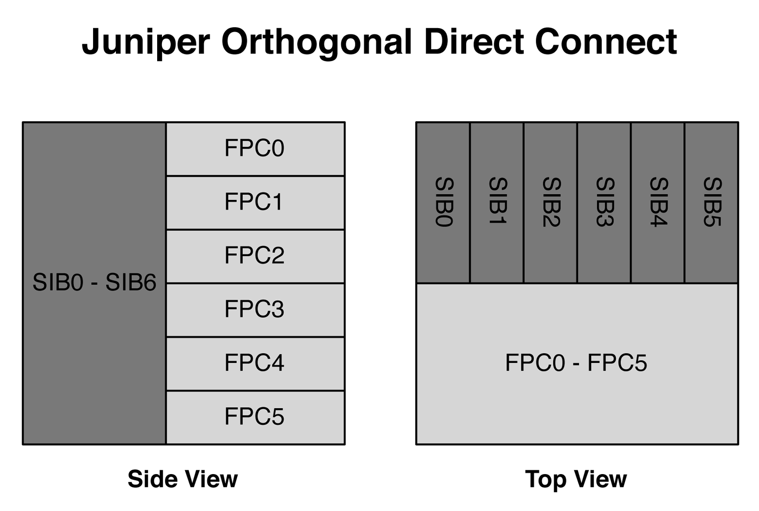
Figure 1-32. Side and top views of Juniper Orthogonal Direct Connect architecture
The top view shows exactly the same thing, but the SIBs in the back of the chassis are now stacked left-to-right. The line cards are stacked on top of one another, but run the entire length of the chassis so that they can directly attach to every single SIB in the system.
To get a full understanding of how the SIBs and FPCs are directly connected to one another, take a look at the front view in Figure 1-33. This assumes that there are four line cards installed into FPC0 through FPC3, whereas FPC4 through FPC7 are empty.
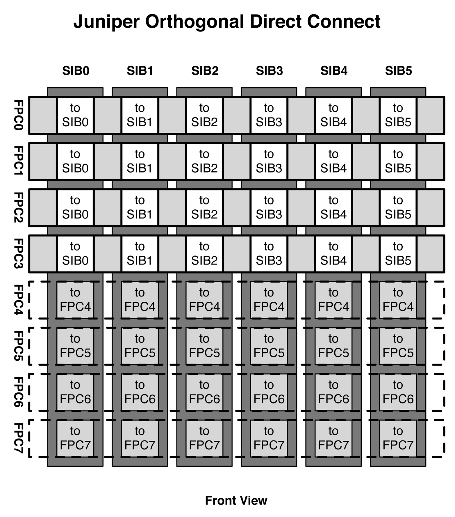
Figure 1-33. Front view of Juniper Orthogonal Direct Connect
The figure shows how the SIBs are installed vertically in the rear of the chassis and the line cards are installed horizontally in the front of the chassis. For example, FPC0 directly connects to SIB0 through SIB5. If you recall in Figure 1-25, there were six connectors in the back of the line card labeled SIB0 through SIB5; these are the connectors that directly plug into the SIBs in the rear of the chassis. In Figure 1-33, the dotted line in the bottom four slots indicates where FPC4 through FPC7 would have been installed. Without the FPCs installed, you can clearly see each SIB connector, and you can see that each SIB has a connector for each of the FPCs. For example, for SIB0, you can see the connectors for FPC4 through FPC7.
In summary, each SIB and FPC is directly connected to each other; there’s no need for outdated mid-plane technology. The benefit is that as long as the SIBs and FPCs are of the same generation, you’ll always get full non-blocking bandwidth within the chassis. For example, as of this writing, the Juniper QFX10000 chassis are running first generation FPCs and SIBs. In the future when there are fourth generation line cards, there will also be fourth generation SIBs that will accommodate the latest line cards operating at full speed. There’s never a mid-plane to slow the system down.
Juniper QFX10008 SIB
The Juniper QFX10008 SIB has two Juniper Q5 Switch Fabric (SF) chips. Each Juniper Q5 SF crossbar can handle 8Tbps of traffic, as shown in Figure 1-34. Each SIB in the Juniper QFX10008 can handle 16Tbps of traffic, which brings the total switching fabric capacity to 96Tbps.
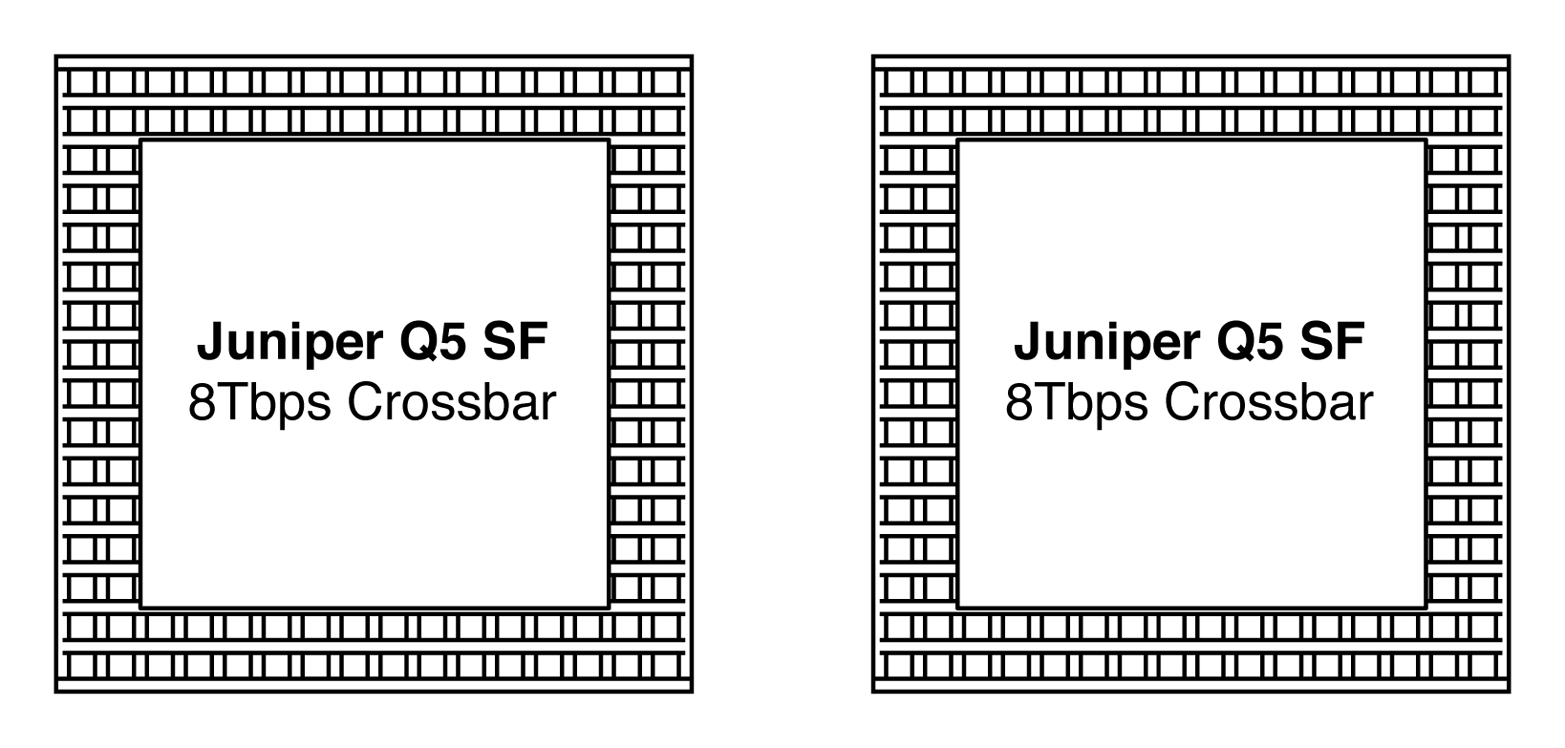
Figure 1-34. Juniper SF crossbar architecture
Each Juniper Q5 SF is attached directly to the line card connectors, so that every Juniper Q5 chip on a line card is directly connected into a full mesh to every single Juniper Q5 SF chip on the SIB, as demonstrated in Figure 1-35.
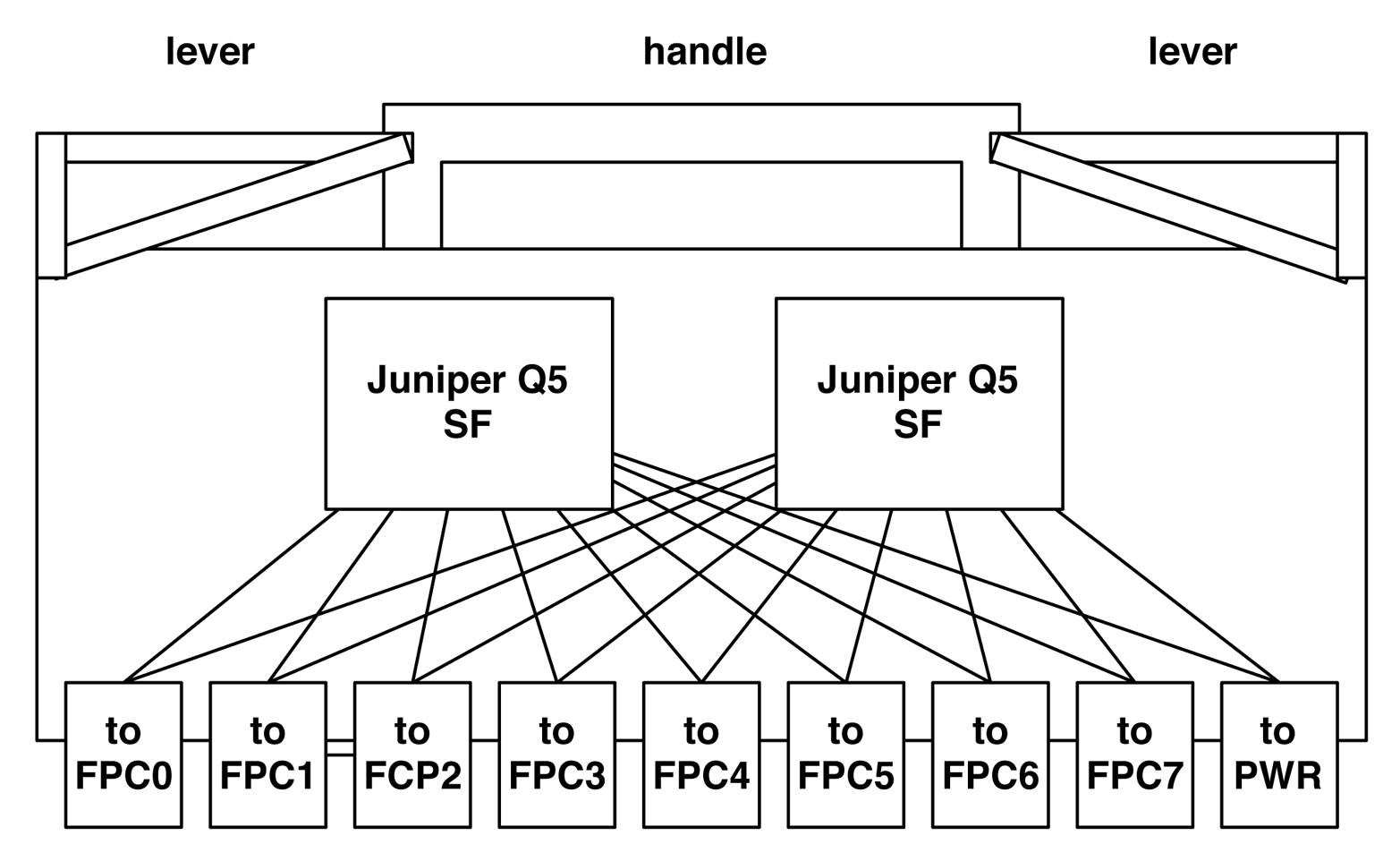
Figure 1-35. Juniper QFX1008 SIB architecture
We can use the Junos command line to verify this connectivity, as well. Let’s take a look at a Juniper QFX10008 chassis and see what’s in the first slot:
dhanks@st-u8-p1-01> show chassis hardware | match FPC0
FPC 0            REV 23   750-051354   ACAM9203          ULC-36Q-12Q28
In this example, we have a QFX1000-36Q line card installed into FPC0. If you recall, each QFX10000-36Q line card has three Juniper Q5 chips. Let’s verify this by using the following command:
dhanks@st-u8-p1-01> show chassis fabric fpcs | no-more
Fabric management FPC state:
FPC #0
    PFE #0
        SIB0_FASIC0 (plane  0)   Plane Enabled, Links OK
        SIB0_FASIC1 (plane  1)   Plane Enabled, Links OK
        SIB1_FASIC0 (plane  2)   Plane Enabled, Links OK
        SIB1_FASIC1 (plane  3)   Plane Enabled, Links OK
        SIB2_FASIC0 (plane  4)   Plane Enabled, Links OK
        SIB2_FASIC1 (plane  5)   Plane Enabled, Links OK
        SIB3_FASIC0 (plane  6)   Plane Enabled, Links OK
        SIB3_FASIC1 (plane  7)   Plane Enabled, Links OK
        SIB4_FASIC0 (plane  8)   Plane Enabled, Links OK
        SIB4_FASIC1 (plane  9)   Plane Enabled, Links OK
        SIB5_FASIC0 (plane 10)   Plane Enabled, Links OK
        SIB5_FASIC1 (plane 11)   Plane Enabled, Links OK
    PFE #1
        SIB0_FASIC0 (plane  0)   Plane Enabled, Links OK
        SIB0_FASIC1 (plane  1)   Plane Enabled, Links OK
        SIB1_FASIC0 (plane  2)   Plane Enabled, Links OK
        SIB1_FASIC1 (plane  3)   Plane Enabled, Links OK
        SIB2_FASIC0 (plane  4)   Plane Enabled, Links OK
        SIB2_FASIC1 (plane  5)   Plane Enabled, Links OK
        SIB3_FASIC0 (plane  6)   Plane Enabled, Links OK
        SIB3_FASIC1 (plane  7)   Plane Enabled, Links OK
        SIB4_FASIC0 (plane  8)   Plane Enabled, Links OK
        SIB4_FASIC1 (plane  9)   Plane Enabled, Links OK
        SIB5_FASIC0 (plane 10)   Plane Enabled, Links OK
        SIB5_FASIC1 (plane 11)   Plane Enabled, Links OK
    PFE #2
        SIB0_FASIC0 (plane  0)   Plane Enabled, Links OK
        SIB0_FASIC1 (plane  1)   Plane Enabled, Links OK
        SIB1_FASIC0 (plane  2)   Plane Enabled, Links OK
        SIB1_FASIC1 (plane  3)   Plane Enabled, Links OK
        SIB2_FASIC0 (plane  4)   Plane Enabled, Links OK
        SIB2_FASIC1 (plane  5)   Plane Enabled, Links OK
        SIB3_FASIC0 (plane  6)   Plane Enabled, Links OK
        SIB3_FASIC1 (plane  7)   Plane Enabled, Links OK
        SIB4_FASIC0 (plane  8)   Plane Enabled, Links OK
        SIB4_FASIC1 (plane  9)   Plane Enabled, Links OK
        SIB5_FASIC0 (plane 10)   Plane Enabled, Links OK
        SIB5_FASIC1 (plane 11)   Plane Enabled, Links OK
We see that FPC0 has three PFEs labeled PFE0 through PFE2. In addition, we see that each PFE is connected to 12 planes across 6 SIBs. Each SIB has two fabric ASICs—the Juniper Q5 SF—which are referred to as a plane. Because there are 6 SIBs with 2 Juniper Q5 SFs each, that’s a total of 12 Juniper Q5 SFs or 12 planes.
The show chassis fabric fpcs command is great if you need to quickly troubleshoot and see the overall switching fabric health of the chassis. If there are any FPC or SIB failures, you’ll see the plane disabled and the links in an error state.
Let’s dig a little bit deeper and see the individual connections between each PFE and fabric ASIC:
dhanks@st-u8-p1-01> show chassis fabric topology

 In-link  : FPC# FE# ASIC# (TX inst#, TX sub-chnl #) ->
            SIB# ASIC#_FCORE# (RX port#, RX sub-chn#, RX inst#)

 Out-link : SIB# ASIC#_FCORE# (TX port#, TX sub-chn#, TX inst#) ->
            FPC# FE# ASIC# (RX inst#, RX sub-chnl #)
SIB 0 FCHIP 0 FCORE 0 :
-----------------------
          In-links               State             Out-links              State
--------------------------------------------------------------------------------
FPC00FE0(1,17)->S00F0_0(01,0,01) OK      S00F0_0(00,0,00)->FPC00FE0(1,09) OK
FPC00FE0(1,09)->S00F0_0(02,0,02) OK      S00F0_0(00,1,00)->FPC00FE0(1,17) OK
FPC00FE0(1,07)->S00F0_0(02,2,02) OK      S00F0_0(00,2,00)->FPC00FE0(1,07) OK
FPC00FE1(1,12)->S00F0_0(01,1,01) OK      S00F0_0(00,3,00)->FPC00FE1(1,06) OK
FPC00FE1(1,06)->S00F0_0(01,2,01) OK      S00F0_0(01,1,01)->FPC00FE1(1,12) OK
FPC00FE1(1,10)->S00F0_0(01,3,01) OK      S00F0_0(01,3,01)->FPC00FE1(1,10) OK
FPC00FE2(1,16)->S00F0_0(00,4,00) OK      S00F0_0(00,4,00)->FPC00FE2(1,08) OK
FPC00FE2(1,08)->S00F0_0(01,6,01) OK      S00F0_0(00,5,00)->FPC00FE2(1,16) OK
FPC00FE2(1,06)->S00F0_0(01,7,01) OK      S00F0_0(00,6,00)->FPC00FE2(1,06) OK
The output of the show chassis fabric topology command is very long, and I’ve truncated it to show only the connections between FPC0 and the first fabric ASIC on SIB0. What’s really interesting is that there are three connections between each PFE on FPC0 and SIB0-F0. Why is that?
Juniper QFX10016 SIB
The Juniper QFX10016 SIB is very similar to the QFX10008 SIB; the only difference is that it has six fabric ASICs instead of two. Each fabric ASIC is directly attached to an FPC connector, as shown in Figure 1-36. The Juniper QFX10016 SIB has 48Tbps of switching capacity because each of the fabric ASICs can handle 8Tbps.
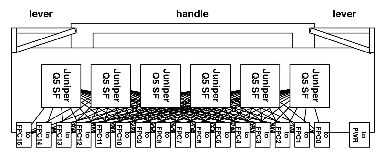
Figure 1-36. Juniper QFX10016 SIB architecture
The reason the Juniper QFX10016 SIB has six fabric ASICs is to handle the additional FPCs in such a large chassis. In the first generation line cards, there could be up to 96 Juniper Q5 chips in a single Juniper QFX10016 chassis. Each PFE has a single connection to every fabric ASIC across all the SIBs.
Optical Support
The Juniper QFX10000 Series supports a wide variety of optics ranging from 1GbE to 100GbE. Each of the optics varies in the distance, speed, and other options.
40GbE
The Juniper QFX10000 supports six different types of 40GbE optics: SR4, ESR4, LR4, LX4, 4x10BASE-IR, and 40G-BASE-IR4. Table 1-6 lists the attributes for each.
| Attribute | SR4 | ESR4 | LR4 | LX4 | 4x10BASE-IR | 40G-BASE-IR4 |
|---|---|---|---|---|---|---|
| Break-out cable | Yes (10GBASE-SR) | Yes (10GBASE-SR) | No | No | No | No |
| Distance | 150M | OM3: 300M OM4: 400M |
10K | OM3: 150M OM4: 150M |
1.4K | 2K |
| Fibers used | 8 out of 12 | 8 out of 12 | 2 | 2 | 8 out of 12 | 2 |
| Optic mode | MMF | MMF | SMF (1310nm) | MMR | SMF (1310nm) | SMF (1310nm) |
| Connector | MTP | MTP | LC | LC | MTP | LC |
| Form factor | QSFP+ | QSFP+ | QSFP+ | QSFP+ | QSFP+ | QSFP+ |
100GbE
The Juniper QFX10000 supports four different types of 100GbE optics: PSM4, LR4, CWDM4, and SR4. Table 1-7 presents their attributes.
| Attribute | PSM4 | LR4 | CWDM4 | SR4 |
|---|---|---|---|---|
| Break-out cable | No | No | No | No |
| Distance | 500M | 10K | 2K | 100M |
| Internal speeds | 4x25GbE | 4x25GbE | 4x25GbE | 4x25GbE |
| Fibers used | 8 out of 12 | 2 | 2 | 8 out of 12 |
| Optic mode | SMF | SMF | SMF | MMF (OM4) |
| Connector | MTP | LC | LC | MTP |
| Form factor | QSFP28 | QSFP28 | QSFP28 | QSFP28 |
Summary
This chapter has covered a lot of topics, ranging from the QFX10002 to the large QFX10016 chassis switches. The Juniper QFX10000 Series was designed from the ground up to be the industry’s most flexible spine switch. It offers incredibly high scale, tons of features, and deep buffer. The sizes range from small 2RU switches that can fit into tight spaces, all the way up to 21RU chassis that are designed for some of the largest data centers in the world. No matter what type of data center you’re designing, the Juniper QFX10000 has a solution for you.
Chapter Review Questions
-
Which interface speed does the Juniper QFX10000 not support?
-
1GbE
-
10GbE
-
25GbE
-
40GbE
-
50GbE
-
100GbE
-
-
Is the QFX10000 a single or multichip switch?
-
Switch-on-a-chip (SoC)
-
Multichip architecture
-
-
How many MAC entries does the QFX10000 support?
-
192K
-
256K
-
512K
-
1M
-
-
How many points in the Juniper Q5 packet-processing pipeline support looping the packet?
-
2
-
3
-
4
-
5
-
-
Which interface within a port group must be configured for channelization?
-
First
-
Second
-
Third
-
Fourth
-
-
What’s the internal code name for the Juniper Q5 chipset?
-
Eagle
-
Elit
-
Paradise
-
Ultimat
-
-
How many switching fabrics are in the QFX10008?
-
2
-
4
-
6
-
8
-
Chapter Review Answers
-
Answer: C and E. The Juniper QFX10000 Series is designed as a spine switch. 25/50GbE are designed as access ports for servers and storage. If you need 25/50GbE interfaces, the Juniper QFX5200 supports it. However, the Juniper QFX10000 focuses on 40/100GbE for leaf-to-spine connections.
-
Answer: B. Each of the Juniper QFX10000 switches use a multichip architecture to provide non-blocking bandwidth for high-scale, large buffers, and tons of features.
-
Answer: B, C, and D. Depending on the QFX10000 switch, the MAC scale is different. The QFX10002-36Q supports 256 K, QFX10002-72Q supports 512 K, and the QFX10008/QFX10016 supports 1 M*.
-
Answer: D. The Juniper Q5 PFE supports looping the packet in five different locations within the ingress to egress PFE pipeline.
-
Answer: A. You must configure the first interface within a port group for channelization. After it is configured, all remaining interfaces within the same port group are also channelized to 4x10GbE.
-
Answer: D. Trick question. The chapter never told you what the name was, but I slipped it into the chapter review questions for the astute reader.
-
Answer: C. The Juniper QFX10008 and QFX10016 support six switching fabric cards to provide non-blocking bandwidth to all of the line cards in a 5 + 1 redundant configuration.
Get Juniper QFX10000 Series now with the O’Reilly learning platform.
O’Reilly members experience books, live events, courses curated by job role, and more from O’Reilly and nearly 200 top publishers.

