The following diagram shows the circuit diagram for this chapter's project:
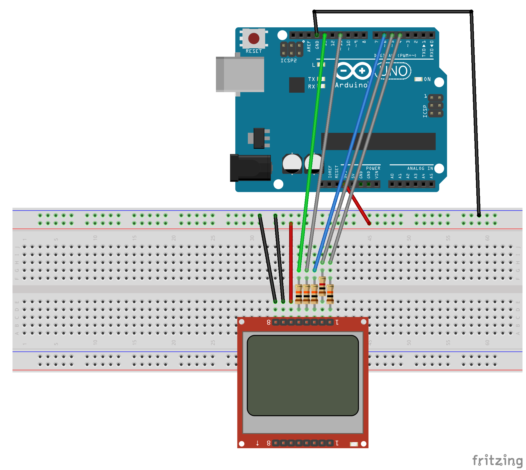
The Nokia 5110 LCD should use the 3.3V power out from the Arduino and not the 5V that we have used in the earlier projects. We use inline resistors to protect the 3.3V input lines on the LCD. The CE line uses a 1K ohm resistor and the remainder use 10K ohm resistors.
The following chart shows what pins on the 5110 LCD module are connected to what pins on the Arduino:
| 5110 | Arduino |
| RST | 3 |
| CE | 4 |
| DC | 5 |
| DIN | 11 |
| CLK | 13 |
| VCC | 3.3V out |
| BL | GND |
| GND | GND |
The backlight is set to ground to turn it off. If you wish to use the backlight, you can connect ...

