The following diagrams show how we would connect an AC-powered device and an Arduino to a relay:
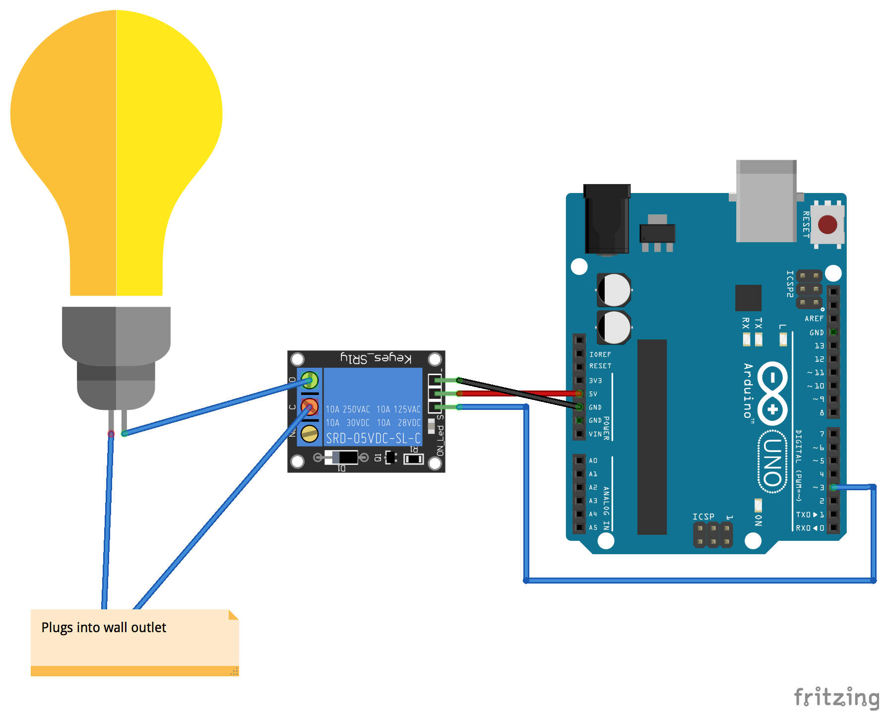
The AC-powered device is connected to the relay as described in the Introduction section. The VCC pin on the relay is connected to the 5V out on the Arduino, and the GND pin on the relay is connected to the GND pin on the Arduino. We connect the digital 3 pin on the Arduino to the pin labeled IN on the relay. The digital 3 pin will be used to control the relay.
The following diagram shows how we would use a relay to control a DC motor and 9V power source with the Arduino:
In preceding circuits, we stressed the need to have a common ...

