APPENDIX H
PENTIUM PINOUT AND PIN DESCRIPTIONS
H.1. Pentium™ Processor Pinout
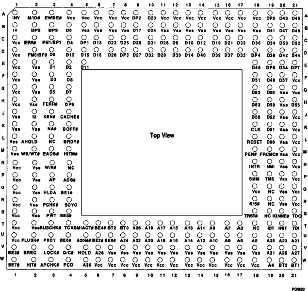
Figure H-1. Pentium™ Processor Pinout(Top View)
Pinout
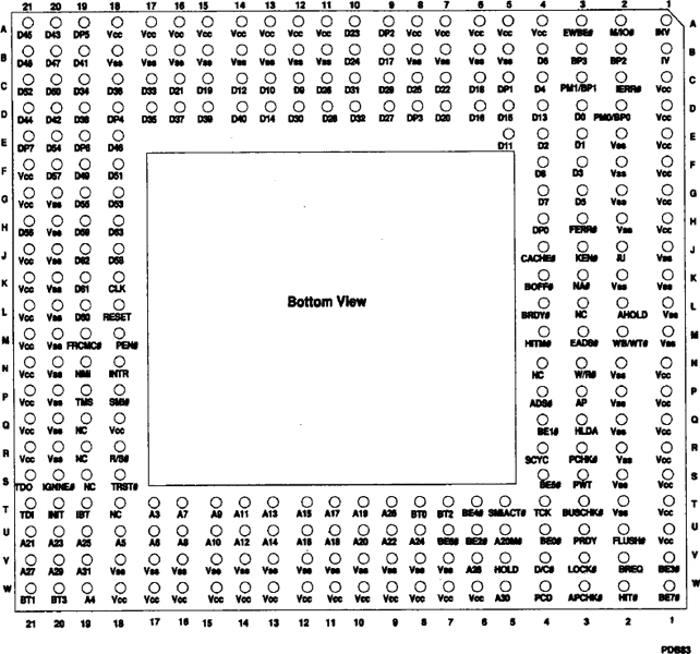
Figure H-2. Pentium™ Processor Pinout (Bottom View)
Table H-1. Pentium™ Processor Pin Cross Reference Table by Pin Name
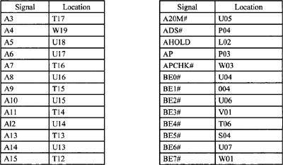
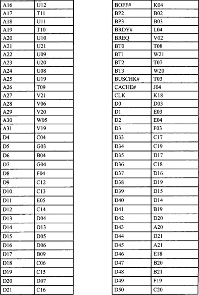
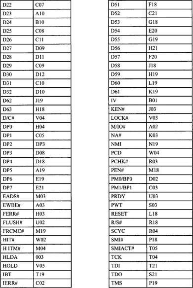
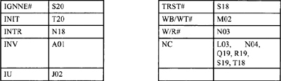
| Signal | Location |
| VCC | A04, A05, F21, G01, R21, S01, W17, W18 A06, A07, A08, A11, A12, A13, A14, A15, A16, A17, A18, 001, D01, E01, G21, H01,J21, K21, L21, M21, N01, N21, P01, P21, 001, 018, 021, R01, T01,U01, W06, W07, W08, W09, W10, W11, W12, W13, W14, W15, W16, W17, W18 |
| VSS | B05, B06, B07, B08, B11, B12, B13, B14, B15, B16, B17, B18, E02, F02, G02, G20, H02, H20, J01, J20, K01, K02, K20, L01, L20, M01, M20, N02, N20, P02, P20, Q02, Q20, R02, R20, S02, T02, V07, V08, V09, V10, V11, V12, V13, V14, V15, V16, V17, V18 |
H.2. Design Notes
For reliable operation, always connect unused inputs to an appropriate signal level. Unused active ...
Get Microprocessor Theory and Applications with 68000/68020 and Pentium now with the O’Reilly learning platform.
O’Reilly members experience books, live events, courses curated by job role, and more from O’Reilly and nearly 200 top publishers.

