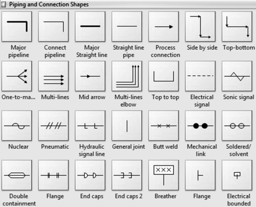
15.16. Piping & instrumentation diagrams (P&IDs)
The P&ID, based on the PFD, represents the technical realization of a process by means of graphical symbols for equipment and piping together with graphical symbols for process measurement and control functions.
The Utility Flow Diagram (UFD) is a special type of a P&ID that represents the utility systems within a process plant, showing all lines and other means required for the transport, distribution, and collection of utilities. The process equipment in the UFD can be represented as a box with inscription (e.g. identification number) and with utility connections.

Get Natural Gas Processing now with the O’Reilly learning platform.
O’Reilly members experience books, live events, courses curated by job role, and more from O’Reilly and nearly 200 top publishers.

