Transforming a Coordinate from the Shader to the Screen
We are now familiar with normalized device coordinates, and we know that in order for a vertex to display on the screen, its x, y, and z components all need to be in the range of [-1, 1]. Let’s take a look at the following flow chart to review how a coordinate gets transformed from the original gl_Position written by the vertex shader to the final coordinate onscreen:
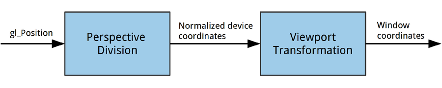
There are two transformation steps and three different coordinate spaces.
Clip Space
When the vertex shader writes a value out to gl_Position, OpenGL expects this position to be in clip space. The logic behind clip space is very ...
Get OpenGL ES 2 for Android now with the O’Reilly learning platform.
O’Reilly members experience books, live events, courses curated by job role, and more from O’Reilly and nearly 200 top publishers.

