54.6. System Designer
The last step in having everything set up to start coding is to plan the deployment for the remaining offices. You have a system ready to be deployed at the corporate headquarters of your hypothetical company. But your planning application will be run from all the plants. The IT department from one of those plants might create an LDD for you to validate your application as shown in Figure 54-5.
Figure 54.5. Figure 54-5

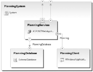
From your Application Diagram you'll create a new system, selecting the applications you'll need to separate as a new deployment unit. In this case choose PlanningServices, PlanningDatabase, and PlanningClient, and then click Design Application System from the context menu. You will have to add two Web Service Consumer Endpoints to the system boundary and connect them to the existing HR and Manufacturing endpoints. Figure 54-6 shows the end result for the planning system.
Figure 54.6. Figure 54-6
This system will be deployed to each plant, so you need to create new Deployment Diagrams. To do this, right-click the designer surface and select Define Deployment. For this example choose the LDD for a hypothetical plant in Sydney. Figure 54-7 shows the final Deployment Diagram for this plant. You can choose to validate to be sure your new system ...
Get Professional Visual Studio® 2008 now with the O’Reilly learning platform.
O’Reilly members experience books, live events, courses curated by job role, and more from O’Reilly and nearly 200 top publishers.

