Dog Assembly
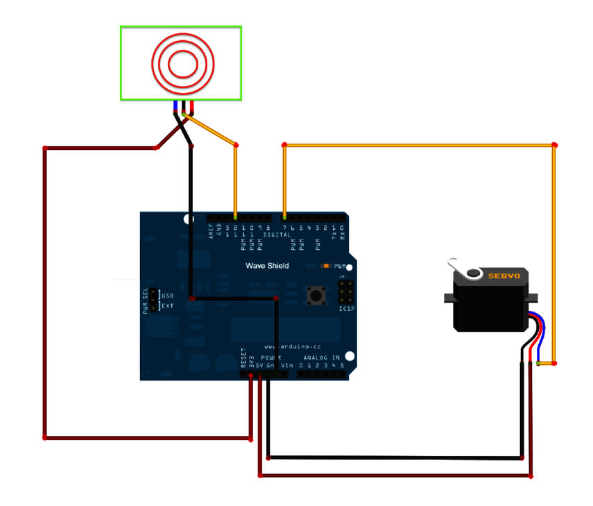
Take a look at the schematic in Figure 8, Wiring diagram for the Electric Guard Dog. The graphic shows wiring plugging into the wave shield. The wave shield is stacked on top of the Arduino board. Note that the wave shield uses several of the pins for its own use to interact with the Arduino, which is why not all passthrough pins are available for the sketch. Closely follow the wiring diagram and you should not have a problem.
Attach the positive lead of the PIR to the 3.3v pin on the wave shield. Connect the negative lead to one of the wave shield’s available ground pins. Then ...
Get Programming Your Home now with the O’Reilly learning platform.
O’Reilly members experience books, live events, courses curated by job role, and more from O’Reilly and nearly 200 top publishers.

