1.4. PROBLEMS WITH TRADITIONAL BUSES
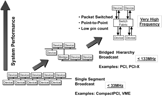
The connections between processors and peripherals have traditionally been shared buses and often a hierarchy of buses (Figure 1.4). Devices are placed at the appropriate level in the hierarchy according to the performance level they require. Low-performance devices are placed on lower-performance buses, which are bridged to the higher-performance buses so they do not burden the higher-performance devices. Bridging may also be used to address legacy interfaces.
Figure 1.4. Higher system performance levels require adoption of point-to-point switched interconnects

Traditional external buses used on more complex semiconductor processing devices such as microprocessors or DSPs are made up of three sets of pins, which are soldered to wire traces on printed circuit boards. These three categories of pins or traces are address, data and control. The address pins provide unique context information that identifies the data. The data is the information that is being transferred and the control pins are used to manage the transfer of data across the bus.
For a very typical bus on a mainstream processor there will be 64 pins dedicated to data, with an additional eight pins for parity protection on the data pins. There will be 32–40 pins dedicated to address with 4 or 5 pins of parity protection on the address pins and there will be approximately another ...
Get RapidIO: The Next Generation Communication Fabric For Embedded Application now with the O’Reilly learning platform.
O’Reilly members experience books, live events, courses curated by job role, and more from O’Reilly and nearly 200 top publishers.

