Chapter 7: Grounding
7.1 Implication of Grounding
Grounding is a common concern in all circuit design for circuit blocks and systems, including RF, digital, and analog circuit designs. As long as the circuit operates in AC mode, grounding must be done properly no matter how low or high the operating frequencies are. In the RF frequency range, grounding becomes a more serious matter because RF frequencies are usually higher than other AC frequencies. Many problems or “bugs” arise from inappropriate grounding. As a matter of fact, grounding is one of the core technologies and an indispensable skill in RF circuit design. In high-speed digital circuit designs, grounding is as important as in RF circuit design.
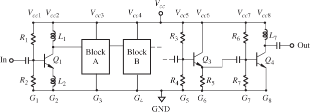
In a circuit block or a system, there are many ground points or nodes marked in a schematic. Figure 7.1 shows a typical way to draw a schematic of circuitry, in which the positive terminal of the DC power supply point is marked with Vcc and the negative terminal of the DC power supply is marked with GND or by an up-side-down symbol “Δ.” The positive terminal of the DC power supply point, Vcc, is connected to many subpoints of DC power supply, Vcc1 to Vcc8, and the negative terminal of the DC power supply point, GND, is connected to many subpoints of ground points, G1 to G8.
Figure 7.1 A typical way to draw a schematic of circuitry.

First, a question is raised: which grounded ...
Get RF Circuit Design, 2nd Edition now with the O’Reilly learning platform.
O’Reilly members experience books, live events, courses curated by job role, and more from O’Reilly and nearly 200 top publishers.

