December 2014
Intermediate to advanced
688 pages
18h 19m
English
A push–pull Class ZVS RF power amplifier with two RF chokes is depicted in Fig. 5.20 [5]. The circuit with the two RFCs can be simplified to the form depicted in Fig. 5.21. This amplifier consists of two transistors, two shunt capacitors ![]() , RFC, center-tapped transformer, and series-resonant circuit driven by the secondary winding of the transformer. The transformer leakage inductance is absorbed into the resonant inductance
, RFC, center-tapped transformer, and series-resonant circuit driven by the secondary winding of the transformer. The transformer leakage inductance is absorbed into the resonant inductance ![]() , and the transistor output capacitances are absorbed into shunt capacitances
, and the transistor output capacitances are absorbed into shunt capacitances ![]() .
.

Figure 5.20 Push–pull Class E ZVS RF power amplifier with two RF chokes [5].
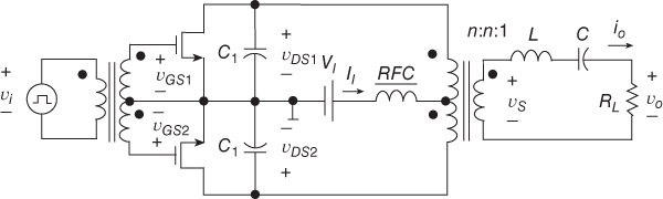
Figure 5.21 Push–pull Class E ZVS RF power amplifier.
Voltage and current waveforms, which explain the principle of operation of the amplifier of Fig. 5.21, are depicted in Fig. 5.22. The dc supply voltage source ![]() is connected through an RFC to the center tap ...
is connected through an RFC to the center tap ...
Read now
Unlock full access


