December 2008
Intermediate to advanced
552 pages
17h 44m
English
This appendix provides closed-form expressions for calculating the characteristic impedance, delay time, and attenuation of traces having microstrip and stripline structures. A procedure for computing analytically the proximity-effect parameter Kp as defined in Chapter 7 is also outlined. Some results are compared with those found in the literature by using field-solver software.
Microstrip has the structure shown in Figure B.1 and is characterized by fields propagating in two different dielectrics: air and substrate with relative permittivity εr. This is particularly true if the trace is not covered by a soldermask to prevent corrosion. Usually, an effective dielectric constant, εre, is used for electric parameter calculations, which is given by
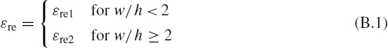
where
![]()

The per-unit-length (p.u.l.) propagation delay time tpd is then given by
![]()
where μ0 = 4π × 10−7 H/m and ε0 = 8.854 × 10⁻¹² F/m.
Figure B.1 Microstrip structure
The microstrip characteristic impedance Z0,ms is given in closed ...
Read now
Unlock full access


