Introduction
Electromagnetic compatibility considers the problems of equipment cohabitation and develops methods to control, predict and resolve the effects of various disturbances:
Signal integrity handles disturbances in the equipment itself: signal distortions during its propagation on networks, from cable to integrated circuit via connectors, printed circuits boards (PCBs) and electronic packages.
Figure I.1. Phenomena to account for in interconnects for signal integrity
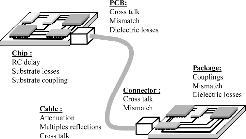
Audio-video applications currently require higher and higher transmission speed and signal processing circuits, which leads to an ever-larger spectral occupation and thus to higher frequencies to be transmitted. At the same time, the presence of multiple parasite phenomena limits the bandwidth of the transmission channel:
Thus, the transmission of the signal across a limited bandwidth transmission channel composed of packages, connectors and lines is manifested by distortions that can ...
Get Signal Integrity: From High Speed to Radiofrequency Applications now with the O’Reilly learning platform.
O’Reilly members experience books, live events, courses curated by job role, and more from O’Reilly and nearly 200 top publishers.

