APPENDIX A
TILTED SMALL-PERTURBATION MODEL DETAILS
Consider a tilted surface element as shown in Figure A.1. The plane of incidence is the (x,z) plane. The coordinate system in which the radar measures the scattering coefficients is the (h,v,k) system and is described by
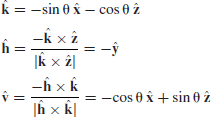
We shall refer to the radar coordinate system as the global coordinate system and the tilted coordinate system as the local coordinate system. The local and global incidence angles are defined as
and
(A.3) ![]()
Figure A.1 Scattering geometry for a tilted surface. The surface is tilted by an angle α in the range (or cross-track) direction and by an angle β in the azimuth (or along-track) direction. The radar measures the scattering coefficients in the global coordinate system, whereas scattering models predict the scattering coefficients in the local coordinate system
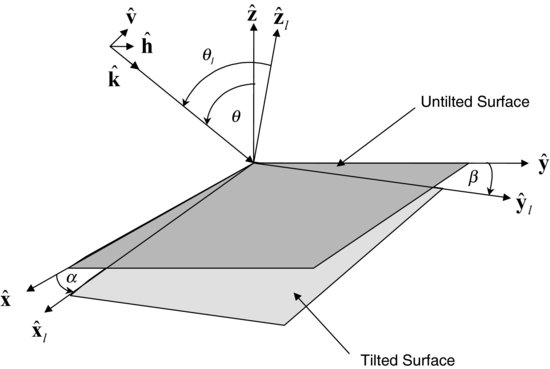
We define the local coordinate system such that the local z-axis coincides with the local normal vector of the tilted surface. Let α denote the tilt angle in the range direction, that is, in the x-z plane. We define positive values of α as ...

