Chapter 1. Service Mesh Fundamentals
Why is operating microservices difficult? What is a service mesh, and why do I need one?
Many emergent technologies build on or reincarnate prior thinking and approaches to computing and networking paradigms. Why is this phenomenon necessary? In the case of service meshes, we’ll look to the microservices and containers movement—the cloud-native approach to designing scalable, independently delivered services as a catalyst. Microservices have exploded what were once internal application communications into a mesh of service-to-service remote procedure calls (RPCs) transported over networks. Bearing many benefits, microservices provide democratization of language and technology choice across independent service teams that create new features quickly as they iteratively and continuously deliver software (typically as a service). The decoupling of engineering teams and their increased speed is the most significant driver of microservices as an architectural model.
Operating Many Services
And, sure, the first couple of microservices are relatively easy to deliver and operate—at least compared to what difficulties organizations face the day they arrive at many microservices. Whether that “many” is 3 or 100, the onset of a major technology challenge is inevitable. Different medicines are dispensed to alleviate microservices headaches; the use of client libraries is one notable example. Language- and framework-specific client libraries, whether preexisting or created, are used to address distributed systems challenges in microservices environments. It’s in these environments that many teams first consider their path to a service mesh. The sheer volume of services that must be managed on an individual, distributed basis (versus centrally as with monoliths) and the challenges of ensuring reliability, observability, and security of these services cannot be overcome with outmoded paradigms, hence the need to reincarnate prior thinking and approaches. New tools and techniques must be adopted.
Given the distributed (and often ephemeral) nature of microservices, and how central the network is to their functioning, it behooves us to reflect on the fallacies that networks are reliable, are without latency, and have infinite bandwidth and that communication is guaranteed (it’s worth reflecting on the fact that these same assumptions are held for service components using internal function calls). When you consider how critical the ability to control and secure service communication is to distributed systems that rely on network calls with every transaction every time an application is invoked, you begin to understand that you are under-tooled and see why running more than a few microservices on a network topology that is in constant flux is so difficult. In the age of microservices, a new layer of tooling for the caretaking of services is needed—a service mesh is needed.
What Is a Service Mesh?
Service meshes provide intent-based networking for microservices describing the desired behavior of the network in the face of constantly changing conditions and network topology. At their core, service meshes provide:
-
A services-first network
-
A developer-driven network
-
A network that is primarily concerned with removing the need for developers to build infrastructure concerns into their application code
-
A network that empowers operators with the ability to declaratively define network behavior, node identity, and traffic flow through policy
-
A network that enables service owners to control application logic without engaging developers to change its code
-
Value derived from the layer of tooling that service meshes provide is most evident in the land of microservices
The more services, the more value derived from the mesh. In subsequent chapters, I show how service meshes provide value outside of the use of microservices and containers and help modernize existing services (running on virtual or bare-metal servers) as well.
Architecture and Components
Although there are a few variants, service mesh architectures commonly comprise three planes: a management plane, a control plane, and a data plane. The concept of these three planes immediately resonates with network engineers by the analogous way physical networks (and their equipment) are designed and managed. Network engineers have long been trained on divisions of concern by planes, as shown in Figure 1-1.
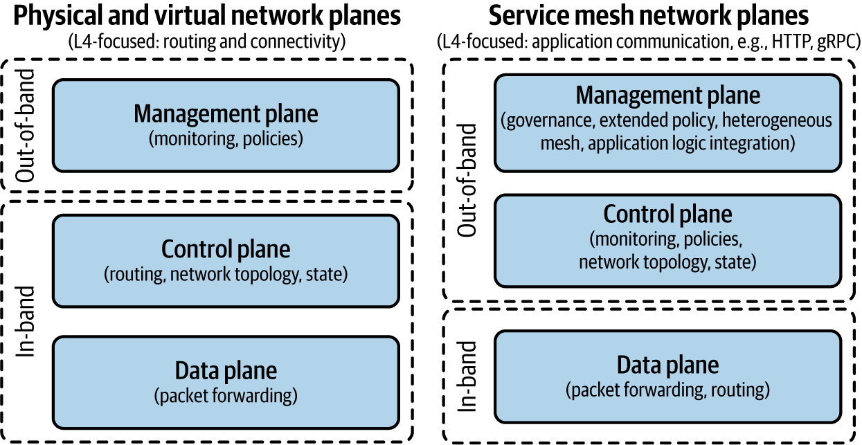
Figure 1-1. Physical networking versus software-defined networking planes
Network engineers also receive training in the OSI model. The OSI model is shown in Figure 1-2, as a refresher for those who have not seen it in some time. We will refer to various layers of this model throughout the book.
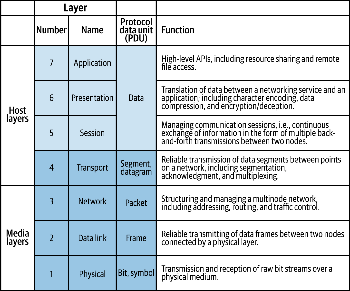
Figure 1-2. Seven-Layer OSI model (source: Wikipedia)
Let’s contrast physical networking planes and network topologies with those of service meshes.
Physical network planes
The physical network data plane (also known as the forwarding plane) contains application traffic generated by hosts, clients, servers, and applications that use the network as transport. Thus, data plane traffic should never have source or destination IP addresses that belong to any network elements such as routers and switches; rather, they should be sourced from and delivered to end devices such as PCs and servers. Routers and switches use hardware chips—application-specific integrated circuits (ASICs)—to forward data plane traffic as quickly as possible. The physical networking data plane references a forwarding information base (FIB). A forwarding information base is a simple, dynamic table that maps a media access control address (MAC address) to a physical network port to transit traffic at wire speed (using ASICs) to the next device.
The physical networking control plane operates as the logical entity associated with router processes and functions used to create and maintain necessary intelligence about the state of the network (topology) and a router’s interfaces. The control plane includes network protocols, such as routing, signaling, and link-state protocols that are used to build and maintain the operational state of the network and provide IP connectivity between IP hosts. Physical network control planes operate in-band of network traffic, leaving them susceptible to denial-of-service (DoS) attacks that either directly or indirectly result in:
-
Exhaustion of memory and/or buffer resources
-
Loss of routing protocol updates and keepalives
-
Slow or blocked access to interactive management sessions
-
High CPU utilization
-
Routing instability, interrupted network reachability, or inconsistent packet delivery
The physical networking management plane is the logical entity that describes the traffic used to access, manage, and monitor all of the network elements commonly using protocols like SNMP, SSH, HTTPS, and, heaven forbid, Telnet. The management plane supports all required provisioning, maintenance, and monitoring functions for the network. Although network traffic in the control plane is handled in-band with all other data plane traffic, management plane traffic is capable of being carried via a separate out-of-band (OOB) management network to provide separate reachability in the event that the primary in-band IP path is not available. Separation of the management path from the data path has the desired effect of creating a security boundary. Restricting management plane access to devices on trusted networks is critical.
Physical networking control and data planes are tightly coupled and generally vendor-provided as a proprietary integration of hardware and firmware. Software-defined networking (SDN) has done much to standardize and decouple. Open vSwitch and OpenDaylight are two examples of SDN projects. We’ll see that control and data planes of service meshes are not necessarily tightly coupled.
Physical network topologies
Common physical networking topologies include star, spoke-and-hub, tree (also called hierarchical), and mesh. As depicted in Figure 1-3, nodes in mesh networks connect directly and nonhierarchically such that each node is connected to an arbitrary number (usually as many as possible or as needed dynamically) of neighbor nodes so that there is at least one path from a given node to any other node to efficiently route data.
When I designed mesh networks as an engineer at Cisco, I did so to create fully interconnected, wireless networks. Wireless is the canonical use case for physical mesh networks when the networking medium is readily susceptible to line-of-sight, weather-induced, or other disruption, and, therefore, when reliability is of paramount concern. Mesh networks generally self-configure, enabling dynamic distribution of workloads. This ability is particularly key to both mitigate risk of failure (improve resiliency) and to react to continuously changing topologies. It’s readily apparent why this network topology, shown in Figure 1-3, is the design of choice for service mesh architectures.
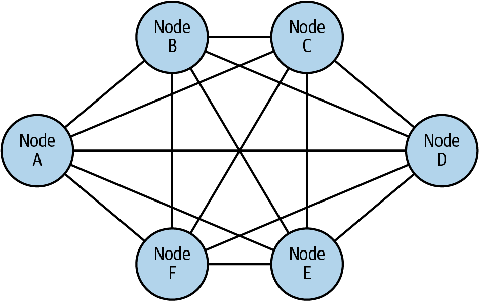
Figure 1-3. Mesh topology—fully connected network nodes
Service mesh network planes
Service mesh architectures typically employ the same three networking planes: data, control, and management (see Figure 1-4).

Figure 1-4. An example of service mesh architecture. In Linkerd’s architecture, control and data planes divide in-band and out-of-band responsibility for service traffic.
A service mesh data plane (otherwise known as the proxying layer) intercepts every packet in the request and is responsible for health checking, routing, load balancing, authentication, authorization, and generation of observable signals. Service proxies are transparently inserted, and as applications make service-to-service calls, applications are unaware of the data plane’s existence. Data planes are responsible for intraservice communication as well as inbound (ingress) and outbound (egress) service mesh traffic. Whether traffic is entering the mesh (ingressing) or leaving the mesh (egressing), application service traffic is directed first to the service proxy for handling prior to sending (or not sending) along to the application. To redirect traffic from the service proxy to the service application, traffic is transparently intercepted and redirected to the service proxy. The interception and redirection of traffic between the service proxy and service application places the service application’s container onto a network it would otherwise not be on. The service proxy sees all traffic to and from the service application (with small exception, this is the case in most service mesh architectures). Service proxies are the building blocks of service mesh data planes.
Traffic Interception and Redirection
Service meshes vary in the technology used to intercept and redirect traffic. Some meshes are flexible as to whether a given deployment uses iptables, IPVS, or eBPF as the technology to transparently proxy requests between clients and service applications. Less transparently, other service mesh proxies simply require that application traffic be configured to direct their traffic to the proxy. The choice between each of these technologies affects the speed in which packets are processed and places environmental constraints on the type and kernel version of the operating system used for the service mesh deployment.
Envoy is an example of a popular proxy used in service mesh data planes. It is also often deployed more simply standalone as a load balancer or ingress gateway. The proxies used in service mesh data planes are highly intelligent and may incorporate any number of protocol-specific filters to manipulate network packets (including application-level data). With technology advances like WebAssembly, extending data plane capabilities means that service meshes are capable of injecting new logic into requests while simultaneously handling high traffic load.
A service mesh control plane is called for when the number of proxies becomes unwieldy or when a single point of visibility and control is required. Control planes provide policy and configuration for services in the mesh, taking a set of isolated, stateless proxies and turning them into a service mesh. Control planes do not directly touch any network packets in the mesh; they operate out-of-band. Control planes typically have a command-line interface (CLI) and/or a user interface for you to interact with the mesh. Each of these commonly provides access to a centralized API for holistically controlling proxy behavior. You can automate changes to the control plane configuration through its APIs (e.g., by a continuous integration/continuous deployment [CI/CD] pipeline), where, in practice, configuration is most often version controlled and updated.
Note
Proxies are not regarded as the source of truth for the state of the mesh. Proxies are generally informed by the control plane of the presence of services, mesh topology updates, traffic and authorization policy, and so on. Proxies cache the state of the mesh but are generally considered stateless.
Linkerd (pronounced “linker-dee”) and Istio (pronounced “Ist-tee-oh”), two popular, open source service meshes, provide examples of how the data and control planes are packaged and deployed. In terms of packaging, Linkerd v1 contains both its proxying components (linkerd) and its control plane (Namerd) packaged together simply as “Linkerd,” and Istio brings a collection of control plane components (Galley, Pilot, and Citadel) to pair by default with Envoy (a data plane) packaged together as “Istio.” Envoy is often labeled a service mesh, but inappropriately so, because it takes packaging with a control plane to form a service mesh.
A service mesh management plane is a higher-order level of control, as shown in Figure 1-5. A management plane may provide a variety of functions. As such, implementations vary in their functionality, some focusing on orchestrating service meshes (e.g., service mesh life-cycle management) and mesh federation, providing insight across a collection of diverse meshes. Some management planes focus on integrating service meshes with business process and policy, including governance, compliance, validation of configuration, and extensible access control.
In terms of deployments of these planes, data planes, like that of Linkerd v2, have proxies that are created as part of the project and are not designed to be configured by hand but are instead designed so their behavior will be entirely driven by the control plane. Other service meshes, like Istio, choose not to develop their own proxy; instead, they ingest and use independent proxies (separate projects), which, as a result, facilitates choice of proxy and its deployment outside of the mesh (standalone). In terms of control plane deployment, using Kubernetes as the example infrastructure, control planes are typically deployed in a separate “system” namespace. Management planes are deployed both on and off cluster, depending on how deeply they integrate with noncontainerized workloads and a business’s backend systems.
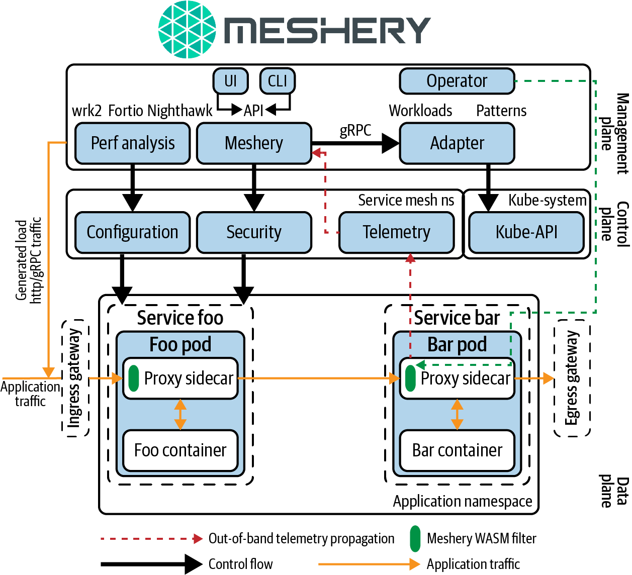
Figure 1-5. Architecture of Meshery, the service mesh management plane
Why Do I Need One?
At this point, you might be thinking, “I have a container orchestrator. Why do I need another infrastructure layer?” With microservices and containers mainstreaming, container orchestrators provide much of what the cluster (nodes and containers) need. Necessarily so, the core focus of container orchestrators is scheduling, discovery, and health, focused primarily at an infrastructure level (networking being a Layer 4 and below focus). Consequently, microservices are left with unmet, service-level needs. A service mesh is a dedicated infrastructure layer for making service-to-service communication safe, fast, and reliable, often relying on a container orchestrator or integration with another service discovery system for operation. Service meshes often deploy as a separate layer atop container orchestrators, but they do not require one because control and data plane components may be deployed independent of containerized infrastructure. As you’ll see in Chapter 3, a node agent (including service proxy) as the data plane component is often deployed in noncontainer environments.
As noted, in microservices deployments, the network is directly and critically involved in every transaction, every invocation of business logic, and every request made to the application. Network reliability and latency are at the forefront of concerns for modern, cloud-native applications. A given cloud-native application might be composed of hundreds of microservices, each of which might have many instances, and each of those ephemeral instances may be rescheduled as necessary by a container orchestrator.
Understanding the network’s criticality, what would you want out of a network that connects your microservices? You want your network to be as intelligent and resilient as possible. You want your network to route traffic around from failures to increase the aggregate reliability of your cluster. You want your network to avoid unwanted overhead like high-latency routes or servers with cold caches. You want your network to ensure that the traffic flowing between services is secure against trivial attacks. You want your network to provide insight by highlighting unexpected dependencies and root causes of service communication failure. You want your network to let you impose policies at the granularity of service behaviors, not just at the connection level. And, you don’t want to write all of this logic into your application.
You want Layer 5 management. You want a services-first network. You want a service mesh.
Value of a Service Mesh
Service meshes provide visibility, resiliency, traffic, and security control of distributed application services. Much value is promised here, particularly to the extent that much is given without the need to change your application code (or much of it, depending).
Observability
Many organizations are initially attracted to the uniform observability that service meshes provide. No complex system is ever fully healthy. Service-level telemetry illuminates where your system is behaving sickly, illuminating difficult-to-answer questions like why your requests are slow to respond. Identifying when a specific service is down is relatively easy, but identifying where it’s slow and why is another matter.
From the application’s vantage point, service meshes provide opaque monitoring of service-to-service communication (observing metrics and logs external to the application) and code-level monitoring (offering observable signals from within the application). Some service meshes work in combination with a distributed tracing library to deliver code-level monitoring, while other service meshes enable a deeper level of visibility through protocol-specific filters as a capability of their proxies. Comprising the data plane, proxies are well-positioned (transparently, in-band) to generate metrics, logs, and traces, providing uniform and thorough observability throughout the mesh as a whole, as seen in Figure 1-6.
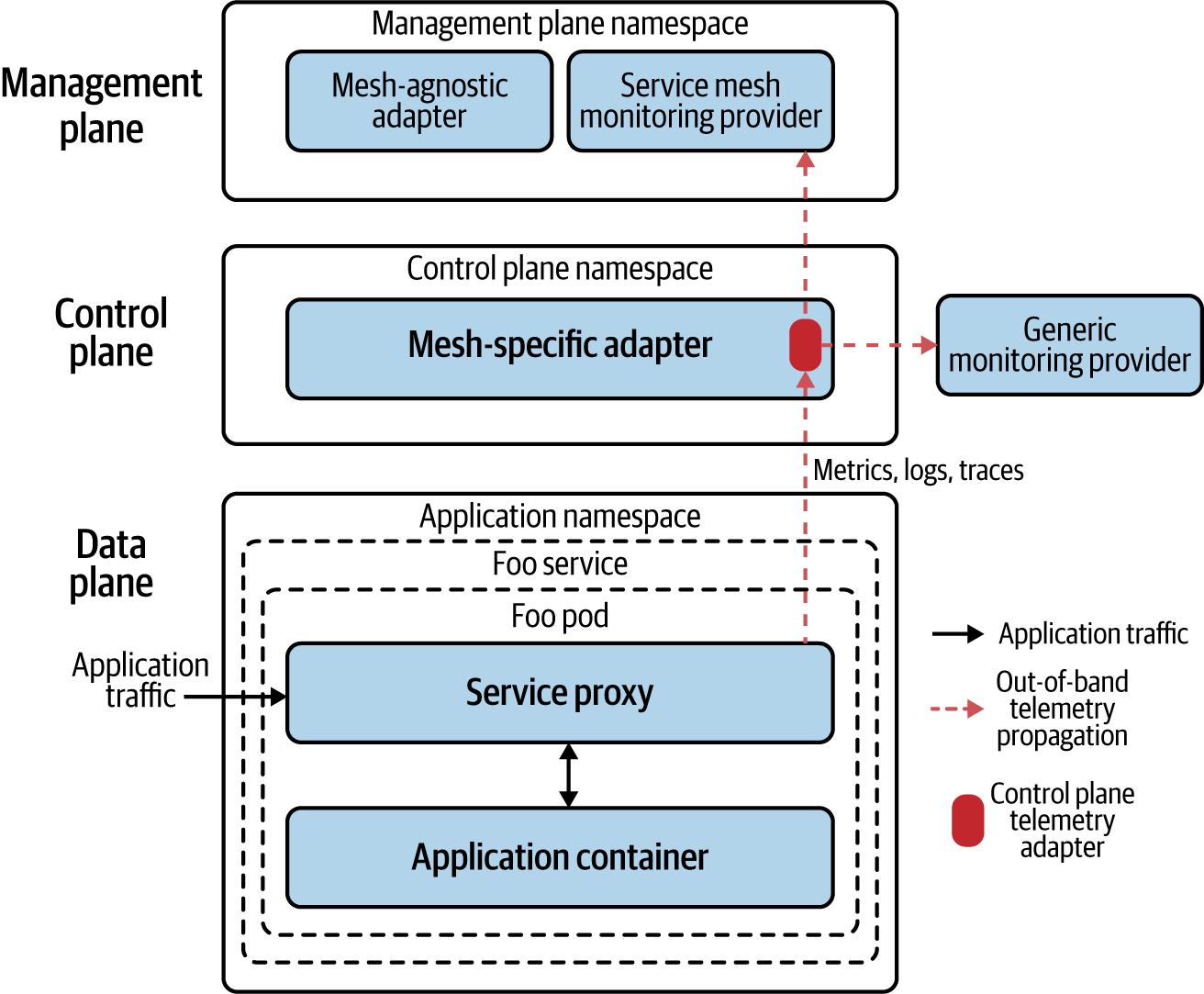
Figure 1-6. Among other things, a service mesh is an accounting machine. Service meshes can collect multiple telemetric signals and send them for monitoring and facilitating decisions such as those dealing with authorization and quota management.
You are probably accustomed to having individual monitoring solutions for distributed tracing, logging, security, access control, and so on. Service meshes centralize and assist in solving these observability challenges by providing the following:
- Logging
-
Logs are used to baseline visibility for access requests to your entire fleet of services. Figure 1-6 illustrates how telemetry transmitted through service mesh logs includes source and destination, request protocol, endpoint (URL), associated response code, and response time and size.
- Metrics
-
Metrics are used to remove dependency and reliance on the development process to instrument code to emit metrics. When metrics are ubiquitous across your cluster, they unlock new insights. Consistent metrics enable automation for things like autoscaling, as an example. Example telemetry emitted by service mesh metrics includes global request volume, global success rate, individual service responses by version, and source and time, as shown in Figure 1-7.
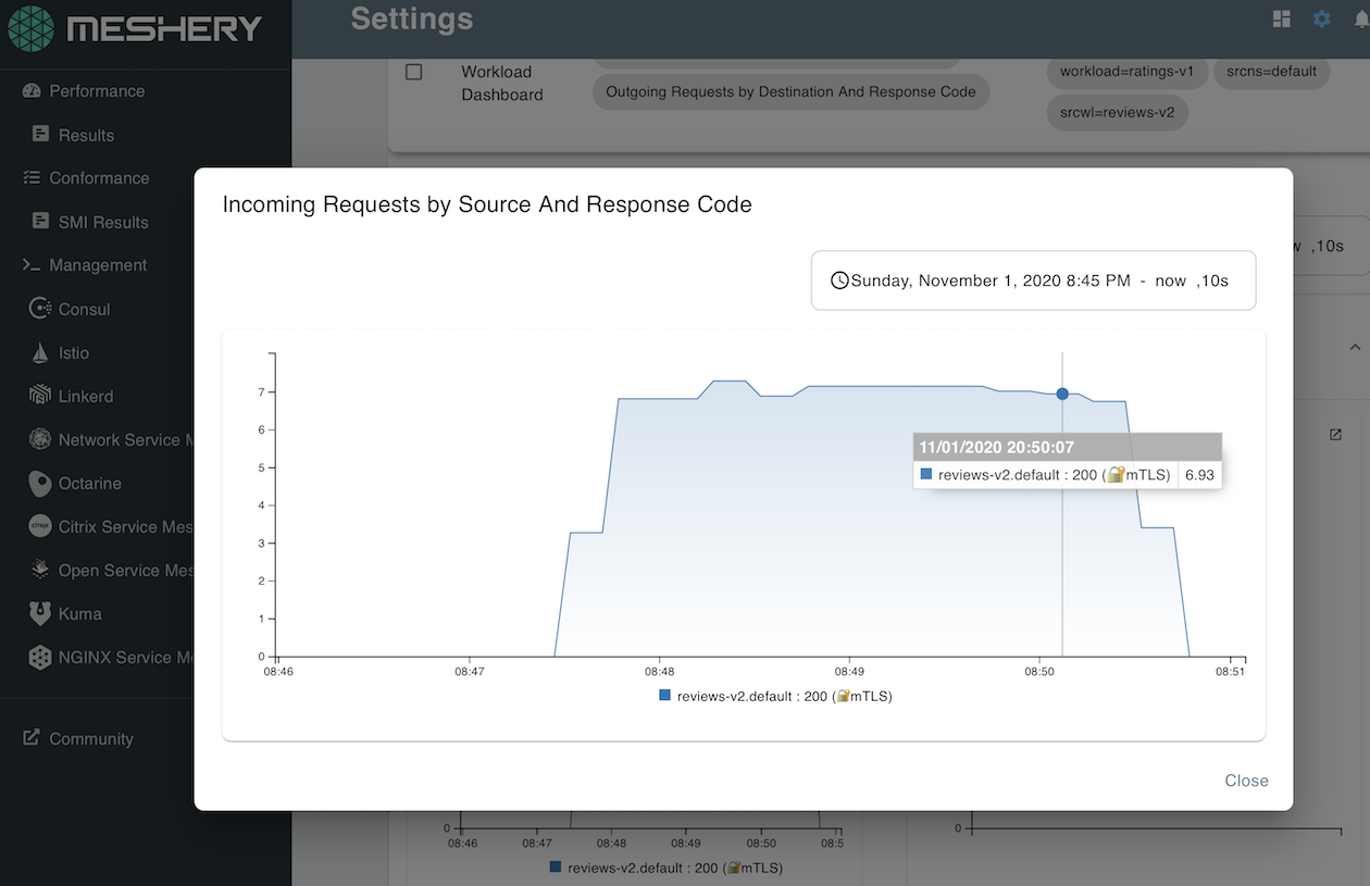
Figure 1-7. Request metrics generated by Istio and visible in Meshery
- Tracing
-
Without tracing, slow services (versus services that simply fail) are difficult to debug. Imagine tracking manual enumeration of all of your service dependencies in a spreadsheet. Traces are used to visualize dependencies, request volumes, and failure rates. With automatically generated span identifiers, service meshes make integrating tracing functionality almost effortless. Individual services in the mesh still need to forward context headers, but that’s it. In contrast, many application performance management (APM) solutions require manual instrumentation to get traces out of your services. Later, you’ll see that in the sidecar proxy deployment model, sidecars are ideally positioned to trace the flow of requests across services.
Traffic control
Service meshes provide granular, declarative control over network traffic to determine where a request is routed to perform canary release, for example. Resiliency features typically include circuit breaking, latency-aware load balancing, eventually consistent service discovery, timeouts, deadlines, and retries.
Timeouts provide cancellation of service requests when a request doesn’t return to the client within a predefined time. Timeouts limit the amount of time spent on any individual request and are enforced at a point in time when a response is considered invalid or too long for a client (user) to wait. Deadlines are an advanced service mesh feature in that they facilitate the feature-level timeouts (a collection of requests) rather than independent service timeouts, helping to avoid retry storms. Deadlines deduct time left to handle a request at each step, propagating elapsed time with each downstream service call as the request travels through the mesh. Timeouts and deadlines, illustrated in Figure 1-8, can be considered as enforcers of your service-level objectives (SLOs).
When a service times out or is unsuccessfully returned, you might choose to retry the request. Simple retries bear the risk of making things worse by retrying the same call to a service that is already under water (retry three times = 300% more service load). Retry budgets (aka maximum retries), however, provide the benefit of multiple tries but with a limit, so as to not overload what is already a load-challenged service. Some service meshes take the elimination of client contention further by introducing jitter and an exponential back-off algorithm into the calculation of timing the next retry attempt.
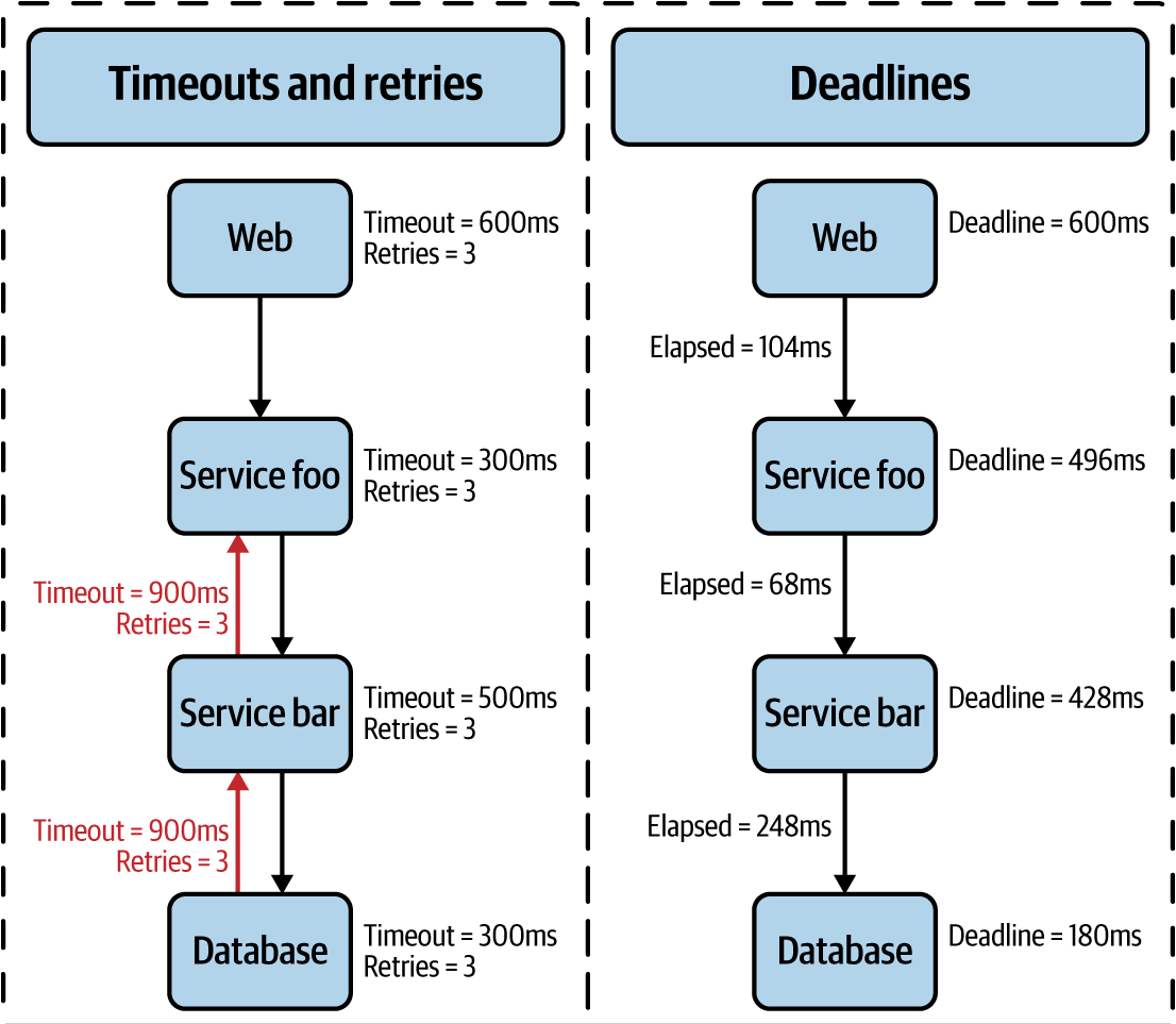
Figure 1-8. Deadlines, not ubiquitously supported by different service meshes, set feature-level timeouts
Instead of retrying and adding more load to the service, you might elect to fail fast and disconnect the service, disallowing calls to it. Circuit breaking provides configurable timeouts (or failure thresholds) to ensure safe maximums and facilitate graceful failure, commonly for slow-responding services. Using a service mesh as a separate layer to implement circuit breaking will avoid excessive overhead on applications (services) at a time when they are already oversubscribed.
Rate limiting (throttling) is used to ensure stability of a service so that when one client causes a spike in requests, the service continues to run smoothly for other clients. Rate limits are usually measured over a period of time, but you can use different algorithms (fixed or sliding window, sliding log, etc.). Rate limits are typically operationally focused on ensuring that your services aren’t oversubscribed.
When a limit is reached, well-implemented services commonly adhere to IETF RFC 6585, sending 429 Too Many Requests as the response code, including headers, such as the following, describing the request limit, number of requests remaining, and amount of time remaining until the request counter is reset:
X-RateLimit-Limit: 60
X-RateLimit-Remaining: 0
X-RateLimit-Reset: 1372016266
Rate limiting protects your services from overuse by limiting how often a client (most often identified by a user access token) can call your service(s), and provides operational resiliency (e.g., service A can handle only 500 requests per second).
A slightly different approach is quota management (or conditional rate limiting), which is primarily used for accounting of requests based on business requirements as opposed to limiting rates based on operational concerns. It can be difficult to distinguish between rate limiting and quota management, given that these two features can be implemented by the same service mesh capability but presented differently to users.
The canonical example of a quota management is to configure a policy setting a threshold for the number of client requests allowed to a service over the course of time, like user Lee is subscribed to the free service plan and allowed only 10 requests per day. Quota policy enforces consumption limits on services by maintaining a distributed counter that tallies incoming requests, often using an in-memory datastore like Redis. Conditional rate limits are a powerful service mesh capability when implemented based on a user-defined set of arbitrary attributes.
Security
Most service meshes provide a certificate authority to manage keys and certificates for securing service-to-service communication. Certificates are generated per service and provide a unique identity of that service. When sidecar proxies are used (discussed later in Chapter 3), they take on the identity of the service and perform life-cycle management of certificates (generation, distribution, refresh, and revocation) on behalf of the service. In sidecar proxy deployments, you’ll typically find that local TCP connections are established between the service and sidecar proxy, whereas mutual Transport Layer Security (mTLS) connections are established between proxies, as demonstrated in Figure 1-9.
Encrypting traffic internal to your application is an important security consideration. Your application’s service calls are no longer kept inside a single monolith via localhost; they are exposed over the network. Allowing service calls without TLS on the transport is setting yourself up for security problems. When two mesh-enabled services communicate, they have strong cryptographic proof of their peers. After identities are established, they are used in constructing access-control policies, determining whether a request should be serviced. Depending on the service mesh used, policy controls configuration of the key management system (e.g., certificate refresh interval) and operational access control are used to determine whether a request is accepted. Allow and blocklist are used to identify approved and unapproved connection requests as well as more granular access-control factors like time of day.
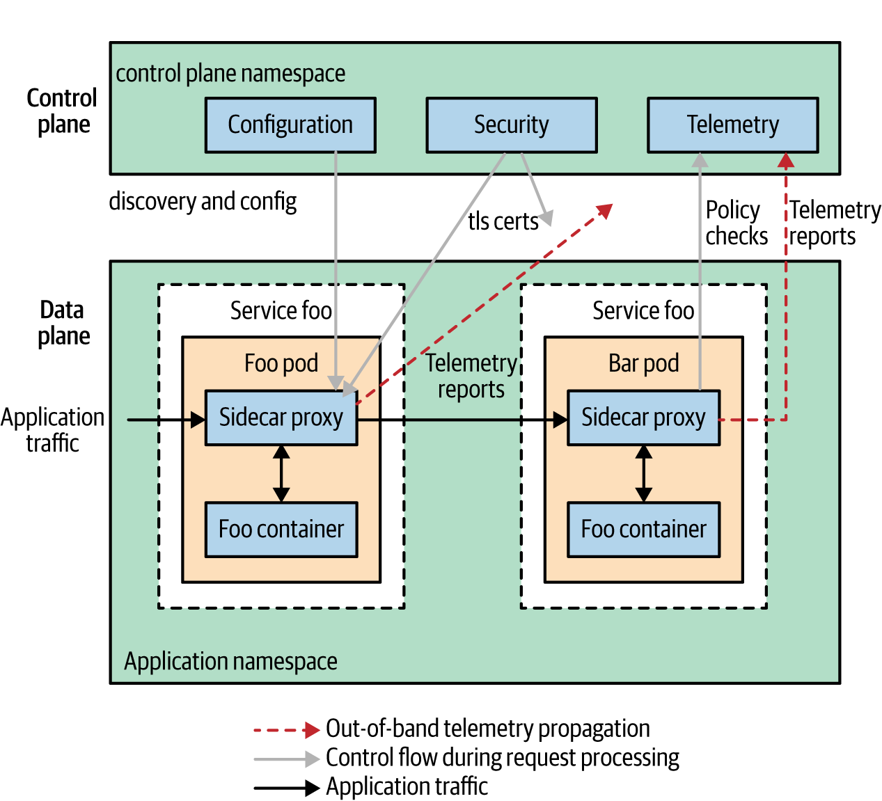
Figure 1-9. An example of service mesh architecture
Delay and fault injection
The notion that your networks and/or systems will fail must be embraced. Why not preemptively inject failure and verify behavior? Given that proxies sit in line to service traffic, they often support protocol-specific fault injection, allowing configuration of the percentage of requests that should be subjected to faults or network delay. For instance, generating HTTP 500 errors helps to verify the robustness of your distributed application in terms of how it behaves in response.
Injecting latency into requests without a service mesh can be a tedious task but is probably a more common issue faced during operation of an application. Slow responses that result in an HTTP 503 after a minute of waiting leave users much more frustrated than a 503 after a few seconds. Arguably, the best part of these resilience testing capabilities is that no application code needs to change in order to facilitate these tests. Results of the tests, on the other hand, might well have you changing application code.
Using a service mesh, developers invest much less in writing code to deal with infrastructure concerns—code that might be on a path to being commoditized by service meshes. The separation of service and session-layer concerns from application code manifests in the form of a phenomenon I refer to as a decoupling at Layer 5.
Decoupling at Layer 5
Service meshes help you avoid bloated service code, fat on infrastructure concerns.
You can avoid duplicative work in making services production-ready by singularly addressing load balancing, autoscaling, rate limiting, traffic routing, and so on. Teams avoid inconsistency of implementation across different services to the extent that the same set of central control is provided for retries and budgets, failover, deadlines, cancellation, and so forth. Implementations done in silos lead to fragmented, nonuniform policy application and difficult debugging.
Service meshes insert a dedicated infrastructure layer between Dev and Ops, separating what are common concerns of service communication by providing independent control over them. The service mesh is a networking model that sits at a layer of abstraction above TCP/IP. Without a service mesh, operators are still tied to developers for many concerns as they need new application builds to control network traffic, change authorization behavior, implement resiliency, and so on. The decoupling of Dev and Ops is key to providing autonomous independent iteration.
Decoupling is an important trend in the industry. If you have a significant number of services, you have at least these three roles: developers, operators, and service owners (product owners). Just as microservices are a trend in the industry for allowing teams to independently iterate, so do service meshes allow teams to decouple and iterate faster. Technical reasons for having to coordinate between teams dissolve in many circumstances, like the following short list of examples:
-
Operators don’t necessarily need to involve developers to change how many times a service should retry before timing out or to run experiments (known as chaos engineering). They are empowered to affect service behavior independently.
-
Customer success (support) teams can handle the revocation of client access without involving operators.
-
Product owners can use quota management to enforce price plan limitations for quantity-based consumption of particular services.
-
Developers can redirect their internal stakeholders to a canary with beta functionality without involving operators.
-
Security engineers can declaratively define authentication and authorization policies, enforced by the service mesh.
-
Network engineers are empowered with an extraordinarily high degree of application-level control formerly unavailable to them.
Microservices decouple functional responsibilities within an application from each other, allowing development teams to independently iterate and move forward. Figure 1-10 shows that in the same fashion, service meshes decouple functional responsibilities of instrumentation and operating services from developers and operators, providing an independent point of control and centralization of responsibility.
Even though service meshes facilitate a separation of concerns, both developers and operators should understand the details of the mesh. The more everyone understands, the better. Operators can obtain uniform metrics and traces from running applications involving diverse language frameworks without relying on developers to manually instrument their applications. Developers tend to consider the network as a dumb transport layer that really doesn’t help with service-level concerns. We need a network that operates at the same level as the services we build and deploy. Because service meshes are capable of deep packet inspection and mutation at the application level, service owners are empowered to bypass developers and affect business-level logic behavior without code change.
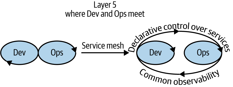
Figure 1-10. Decoupling as a way of increasing velocity
Essentially, you can think of a service mesh as surfacing the session layer of the OSI model as a separately addressable, first-class citizen in your modern architecture. As a highly configurable workhorse, the service mesh is the secret weapon of cloud-native architectures, waiting to be exploited.
Conclusion
The data plane carries the actual application request traffic between service instances. The control plane configures the data plane, provides a point of aggregation for telemetry, and also provides APIs for modifying the mesh’s behavior. The management plane extends governance and backend systems integration and further empowers personas other than strictly operators while also significantly benefitting developers and product/service owners.
Decoupling of Dev and Ops avoids diffusion of the responsibility of service management, centralizing control over these concerns in a new infrastructure layer: Layer 5.
Service meshes make it possible for services to regain a consistent, secure way to establish identity within a datacenter and, furthermore, do so based on strong cryptographic primitives rather than deployment topology.
With each deployment of a service mesh, developers are relieved of their infrastructure concerns and can refocus on their primary task (creating business logic). More-seasoned software engineers might have difficulty breaking the habit and trusting that the service mesh will provide, or even displacing the psychological dependency on their client libraries.
Many organizations find themselves in the situation of having incorporated too many infrastructure concerns into application code. Service meshes are a necessary building block when composing production-grade microservices. The power of easily deployable service meshes will allow for many smaller organizations to enjoy features previously available only to large enterprises.
Get The Enterprise Path to Service Mesh Architectures, 2nd Edition now with the O’Reilly learning platform.
O’Reilly members experience books, live events, courses curated by job role, and more from O’Reilly and nearly 200 top publishers.

