Chapter 1
Basic Skills and Concepts Having Application to Transmission Lines
We are rapidly moving into a digital era. Until as recently as some 10 years ago, clock speeds and data rates of digital systems were in the hundreds of megahertz (MHz) range, with rise and fall times of the pulses in the nanosecond (![]() ) range. Prior to that time, the lands (conductors of rectangular cross section) that interconnect the electronic modules on printed circuit boards (PCBs) had little or no impact on the proper functioning of those electronic circuits. Today, the clock and data speeds have moved rapidly into the low-gigahertz (GHz) range. The rise and fall times of those digital waveforms have decreased into the picosecond (
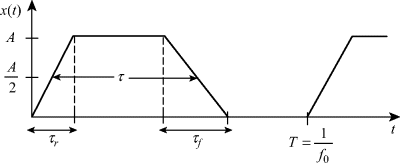
) range. Prior to that time, the lands (conductors of rectangular cross section) that interconnect the electronic modules on printed circuit boards (PCBs) had little or no impact on the proper functioning of those electronic circuits. Today, the clock and data speeds have moved rapidly into the low-gigahertz (GHz) range. The rise and fall times of those digital waveforms have decreased into the picosecond (![]() ) range. For example, a 1-GHz digital clock signal consists of trapezoidal-shaped pulses having rise and fall times on the order of 100 ps or less. A digital clock waveform is illustrated in Fig. 1.1.
) range. For example, a 1-GHz digital clock signal consists of trapezoidal-shaped pulses having rise and fall times on the order of 100 ps or less. A digital clock waveform is illustrated in Fig. 1.1.
Figure 1.1 Typical digital clock/data waveform.

The period of the periodic waveform T is the reciprocal of the clock fundamental frequency ![]() . The rise and fall times are denoted ...
. The rise and fall times are denoted ...

