Chapter 3
Frequency-Domain Analysis of Two-Conductor Lines
In this chapter we examine the response of a two-conductor transmission line to a single-frequency sinusoidal source ![]() or
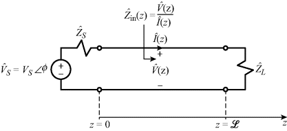
or ![]() . We assume that the source has been applied for a sufficient length of time so that the line response voltages and currents have reached steady state. In other words, we examine the phasor response of the line, as illustrated in Fig. 3.1. So we replace the time-domain source with the phasor source:
. We assume that the source has been applied for a sufficient length of time so that the line response voltages and currents have reached steady state. In other words, we examine the phasor response of the line, as illustrated in Fig. 3.1. So we replace the time-domain source with the phasor source:
(3.1) 
Figure 3.1 Phasor response of the two-conductor line.

The line voltages and currents are (complex-valued) phasors with a magnitude and an angle that we denote with carets:
(3.2a) ![]()
(3.2b) ![]()
3.1 The Transmission-Line Equations for Sinusoidal Steady-State Excitation of the Line
The time-domain derivatives are replaced with :
(3.3)
where the radian frequency of the source is and f is its cyclic frequency in hertz. ...

