
Drawing Pictures
If you are one of those who can’t draw a straight line, let alone a decent picture or graph, you probably replace pictures with verbal descriptions. Perhaps you know what it is like to describe a drawing to a person who knows how to draw. The pic preprocessor requires you to follow the process of using “words” to describe something pictorial.
The pic preprocessor has a dual purpose. The first is to provide a “natural language” method of describing simple pictures and graphs in your documents. The second is to offer a “programming language” for generating pictures and graphs with minimal user input. Learning pic is an iterative process: describe what you want and then look at what you get. We have included many examples that show both the description and the resulting picture or graph. Take the time to create variations of these descriptions, making modifications and improvements.
The pic preprocessor was designed to produce output on a typesetter, which makes pic expensive and difficult to learn. Fortunately, some graphics terminals and most laser printers can be set up to display or print pic drawings. Access to one or the other is essential if you are going to get enough practice to know how pic responds.
As a preprocessor, pic is a program that processes a specific portion of an input file before the whole document goes to the troff formatter. (The nroff formatter cannot produce pic output for terminals or line printers.) The preprocessors translate your description into low-level formatter requests for troff.
Just like with tbl and eqn, a pair of macros in the input file mark the beginning and end of input to be processed by pic. The delimiters for pic are:
.PSpic description.PE
When you format a document that contains pic descriptions, you must invoke the pic preprocessor as follows:
$ pic file | troff | device
▪ The pic Preprocessor ▪
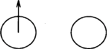
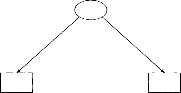
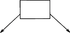
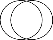
Imagine that you have to describe over the telephone the following picture:
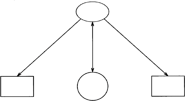
You might say: “There’s an ellipse at the top. Arrows are connected to two boxes and a circle below it.” Now, think about describing this picture to someone who is attempting to draw it. No matter how careful you are, you realize that it is difficult to translate a drawing into words.
“First, draw an ellipse. Move down and draw a circle below it. Then draw one box to the left and draw another box of the same size to the right. Then draw an arrow from the bottom of the ellipse to the top of the left-hand box. Then draw a line from the bottom of the ellipse to the top of the right-hand box. The last thing to do is draw a line between the circle and the ellipse and put arrowheads on both ends.”
Here’s what the actual pic description looks like:
.PS

down

ellipse

move down 1.25

circle radius .35

move left li from left of last circle; box

move right li from right of last circle; box

arrow from lower left of last ellipse to top of 1st box

arrow from lower right of last ellipse to top of 2nd box

arrow <-> from bottom of last ellipse to top of last circle

.PE
Even though you may know nothing about pic, you should be able to make some sense out of this description. It names several objects: an ellipse, two boxes, a circle, and three arrows. It specifies motion in inches as well as changes in direction. It also arranges some objects in relation to others, locating the boxes to the left and right of the circle and drawing arrows between the ellipse and the circle.
Having seen a full description of a pic drawing in this example, you should be able to get something of the flavor of pic. The simpler the drawing, the less explaining you have to do. We won’t go into any more detail about this pic description right now. We’ll look at it later in this chapter after we’ve covered the basics of the pic language.
Naming Objects
The pic program is easy to use if you are describing only a single box or a circle. To draw a circle, you name that object within the .PS/.PE macros:
.PS

circle

.PE
When this description is processed by pic it produces:

There are seven graphics primitives: arc, arrow, box, circle, ellipse, line, and spline. We will show these primitives in examples that present additional aspects of pic.
In using a computer language, you have to be precise, using as few words as possible to get the picture you want. This means that you allow the program to make as many of the decisions about the drawing as is practical. After you understand pic’s normal behavior, you will know what pic will do on its own.
For instance, we didn’t specify the size of the circle in the last example. By default, pic draws a circle with a diameter of ½ inch (or a radius of .25 inch). You can get a circle of a different size, but you have to specify the size.
.PS

circle radius .5

.PE
The pic program understands any number to be in inches. You specify the size of a circle by giving its radius, which can be abbreviated as rad, or its diameter, which can be abbreviated as diam. The previous input produces a circle twice the size of the standard circle:
Similarly, if you specify box, you will get a box with a height of .5 inch and a width of .75 inch. You can get a larger or smaller box by changing its dimensions:
.PS

box height li width .5

.PE
The output for this example is a box twice as high as it is wide:
You can also use the abbreviations ht and wid for these attributes. The order in which you specify the dimensions does not matter, and you can change one attribute without changing the other. That is how we can draw a square:
.PS

box ht .75

.PE
The default width is already .75 inch, so this pic description produces:

With the attribute same, you can reuse the dimensions specified for a previous object of the same type. For instance, after you had described the square box, box same would duplicate a square of the same size.
Labeling Objects
To provide a label for any object, specify the text within double quotation marks after the name of the object. The label is placed at the center of the object.
.PS

box ht .75 "Square One"

.PE
This pic description produces:
Even if a label does not contain blank spaces, you must enclose it within double quotation marks. Each individually quoted item will be output on a new line.
box wid .5 "Second" "Square"
This description produces:

Because troff, not pic, actually handles the text, pic doesn’t really try to fit a label inside an object. You must determine the amount of text that will fit. The pic program ignores lines beginning with a period, permitting you to use troff requests to change the point size, font, or typeface. It is best to avoid spacing requests, and be sure to reset any change in point size.
When you specify a single text label with a line, pic centers it on the line. For instance, inline troff requests can be used to print a label in 14-point italic (i.e., 4 points larger than the current point size).
.PS

line "\fI\s14pic\s10\fR"

.PE
It produces:
![]()
Because the standard placement of labels is not always useful, you can specify the attributes above or below. In the following example, the point size is specified using the following .ps request:
It produces:
![]()
If you supply two quoted arguments with line, the first will be printed above the line and the second printed below.
You can also select a line or box that is dotted or dashed, as you can see in the next example:
box dotted "\f(CWbox dotted\fP" above
Note the inline request to invoke the constant-width font for the label. The above keyword places the label above the center line of the box. This description produces:
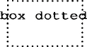
The box, composed of dots, contains a label printed in constant-width font. It is obvious here that pic made no attempt to fit the label “inside” the box. The above attribute does not place text above the box, but rather above the center of the box. The description:
line dashed "sign here" below
produces a dashed line:
![]()
If the attributes of texture are followed by a value, pic will try to keep that amount of spacing between the dashes or dots. The description dashed .1 will result in dashes spaced .1 inch apart.
pic’s Drawing Motion
After you have named an object and determined its size, you have to think about where pic is going to draw it. (Indentation and other matters concerning the placement of the drawing on the page are supplied by either the .PS/.PE or .DS/.DE macros. The pic program places a single object at the left margin. If you name three objects in the same description, where will pic draw them?
The following output is produced:
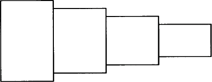
Objects are placed one after another from left to right. The pic program assumes that objects should be connected, as in the following example:
.PS

box ht 1.25

box ht 1

box ht .75

box ht .5

.PE
This description produces a row of boxes of decreasing size:
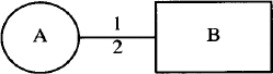
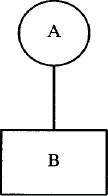
If you don’t want objects to be connected, you can move before specifying the next object. In the next example, move places a box to the right of a circle:
.PS

circle "A" ; move; box "B"

.PE
As shown in this example, pic commands can be entered on the same line, separated by semicolons, instead of on separate lines. This description produces:
Changing Direction
As you have seen, pic places objects in a continuous motion from left to right. You can also get pic to change direction using the attributes left, right, up, or down. We’ll see examples of their use shortly.
The distance of a move is the same length as a line (.5 inch). If you want to change the distance of a move or the length of a line, then the change must be accompanied by an attribute of direction. Although it seems natural to write:
line 2; move 1; arrow 1 Wrong
pic does not accept this command unless you specify directions for all three cases. When pic objects to your choice of words, it will display the offending line, using a caret (^) to mark the error.
pic: syntax error near line 1, file test

 context is

       line 2 ^; move 1
Only the first error on the line is marked. (It is acceptable to write line; move, using the standard length and distance.) The next example shows how to draw a line of a specified length and how to move a specified distance. The pic program assumes that any value is in inches; thus you can say 2i or simply 2 to indicate 2 inches.
line up 2; move down 1; arrow right 1
Note that the attribute of direction precedes the distance. The preceding description produces:
You cannot specify down 1 or right 1 without also specifying either a line or move. These attributes change the direction of the motion used to draw objects. They do not cause movement. The attributes of direction affect the position of the objects that follow it, as shown in the next example.
These objects are drawn from top to bottom:
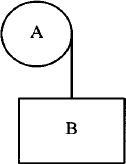
If you describe a change of motion, it affects the points where objects are connected. Look what happens if we specify the attribute down after the circle:
.PS

circle "A"; down; line; box "B"

.PE
Now the line begins at a different position:
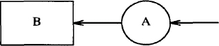
The pic program keeps track of the start and end points for each object, and their relationship to the direction in which objects are being drawn. The next object is drawn from the exit point of the previous object. Entry and exit points may seem obvious for a line, but not so obvious with circles. When the motion is from left to right, a circle’s entry point is at 9 o’clock and its exit point is at 3 o’clock. When we specified down after the circle in the first example, the exit point of the circle did not change; only the direction in which the line was drawn from that point changed. Entry and exit points are reversed when the motion is from right to left, as specified by the left attribute.
This description produces:
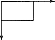
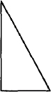
You can draw a diagonal line by applying two changes in direction. Look at how we describe a right triangle:
.PS

line down li

line right li

line up li left li

.PE
This description produces:
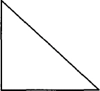
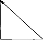
The diagonal line is drawn by combining two attributes of direction, up and left. You can describe a continuous line using then. In the next example we use arrow to demonstrate that we are describing a single object.
.PS

arrow down li then right li then up li left li

.PE
When using then, you have to define the motion on a single line or escape the end of the line with a backslash (\). It produces:
If the description ended with:
we would have a 1-inch square instead of a right triangle.
An arc is a portion of a circle. Naming four arcs consecutively will draw a circle. An arc is drawn counterclockwise from the current position (from 6 o’clock to 3 o’clock, for instance). The next example uses arcs to produce a box with rounded corners:
line right 1; arc; line up ; arc

line left 1; arc; line down; arc
This description starts with the bottom line of the curved box. The motion is counterclockwise.

The attribute cw draws an arc in a clockwise direction:
arc "A"; arc "B" cw
This description produces:

Note that text is placed at what pic considers to be the center of the arc, which is the center of the corresponding circle.
A spline is a cross between an arc and a line. It is used to draw smoothed curves. In this example, a spline traces a path between two circles.
circle rad .25

spline right 1 then down .5 left 1 then right 1

circle same
This description produces:
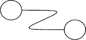
A spline is used in the same way as a line. When drawn continuously using then, a spline that changes direction draws a curve. (Similarly, a line would produce an angle.) We’ll see more examples of spline later.
Placing Objects
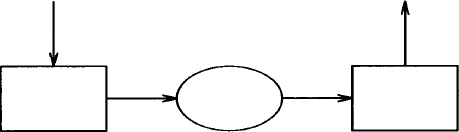
It isn’t always useful to place objects in a continuous motion. Look at the following example, which seems like it ought to work but doesn’t:
.PS

down; arrow; box

right; arrow; ellipse; arrow

.PE
This pic description produces:
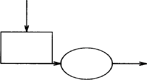
Note the short arrow, drawn from the box to the circle. What happened? The end point of the box was not on the right, but on the bottom, because the motion in effect where the box is drawn is down. Changing direction (right) affects only the direction in which the arrow is drawn: it does not change where the arrow begins. Thus, the arrow is drawn along the bottom line of the box.
Sometimes, it is best to place an object in relation to previously placed objects. The pic program provides a natural way to locate objects that have been drawn. For example, the attribute first locates the first occurrence of an object, and the attribute from specifies that the object serves as a starting point for the next object drawn.
.PS

circle ; move; circle ; arrow up from first circle

.PE
It produces:
You can reference each type of object using an ordinal number. Referring to the order in which an object is drawn, you can say first box (1st box is also acceptable) or 2nd circle. You can also work back from the last object, specifying the last box or 2nd last box.
The center of each object is used as the reference point. In the last example, the arrow was drawn from the center of the circle. The attribute chop can be used to chop off the part of the line that would extend to the center of each circle. In the next example, a chopped line is drawn between the first and third circles:
.PS

circle "1" ; move down from last circle

circle "2"; move right from last circle; circle "3"

line from 1st circle to last circle chop

.PE
This description produces:
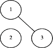
The amount that is chopped is by default equal to the radius of the circle. You can specify how much of the line is chopped, for use with other objects or text, by supplying either one or two values after the attribute. If a single value is given, then both ends of the line are chopped by that amount. If two values are given, the start of the line is chopped by the first amount and the end of the line chopped by the second amount.
It is important to remember that movement from a referenced object is measured from its center, unless otherwise specified. Look at these four circles:
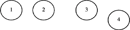
The second circle is produced by the description:
move right from last circle; circle "2"
Because the distance (.5 inch by default) is measured from the center of the circle, there is only .25 inch between the two circles. The third circle is produced by the description:
Now the distance is measured from the right of the second circle. There is twice as much space between the second and third circle as between the first and second. The fourth circle is produced by the description:
move right from bottom of last circle; circle "4"
The starting point of the fourth circle (its left “side”) is .5 inch right from the bottom of the previous circle.
Using bottom, top, right, and left, you can locate specific points on any object. In the next example, we solve the problem of turning a corner by specifying the place from which the arrow will be drawn:
.PS

down; arrow; box

right; arrow from right of last box; ellipse; arrow ; box

up; arrow from top of last box

.PE
In our earlier example, the arrow was drawn from the bottom of the box; now we change the starting point of the arrow to the right of the previous box. This description produces:
With boxes and ellipses, you can refer to an upper or lower position:
.PS

box; arrow from upper right of last box;

arrow down from lower left of last box

.PE
This description produces:
With objects like lines and arcs, it is more useful to refer to the start and end of the object. For example, here’s another way to draw a triangle:
.PS

line down li

line right

line from start of 1st line to end of 2nd line

.PE
The last line could also be written:
line to start of 1st line
The pic description produces:
You now know enough of the basic features of pic to benefit from a second look at the pic description shown at the beginning of this chapter. The only thing we haven’t covered is how to get a double-headed arrow. Because an arrow can also be specified as line –> or line <–, you can get a double-headed arrow with line <–>.
.PS

1    down

2    ellipse

3    move down 1.25

4    circle radius .35

5    move left li from left of last circle; box

6    move right li from right of last circle; box

7    arrow from lower left of last ellipse to top of \ 1st box

8    arrow from lower right of last ellipse to top of \ 2nd box

9    line <-> from bottom of last ellipse to top of last \ circle

.PE
The lines in this description are numbered for easy reference in the following exercise.
As is true with almost anything you describe, a pic description could be written in several different ways. In fact, you will learn a lot about pic by making even minor changes and checking the results. See if you can answer these questions:
![]() Why is
Why is down specified before the ellipse? If you removed down, would the circle be centered underneath the ellipse?
![]()
down changes direction of movement. Does pic allow you to say move 1.25 as well as move down 1.25?
![]() Where is the exit point of the
Where is the exit point of the circle when it is drawn with a downward motion in effect? If lines 5 and 6 were replaced by:
move left li; box

move right 2i; box
where would the boxes be drawn?
![]() There is 1 inch between the circle and each box. How much space would there be if lines 5 and 6 were replaced by:
There is 1 inch between the circle and each box. How much space would there be if lines 5 and 6 were replaced by:
move left from last circle; box

move right from last circle; box
Hint: The distance of a move is .5 inch, and this would be measured from the center of the circle, which has a radius of .35 inch.
![]() Line 8 draws an arrow from the lower right of the ellipse to the top of the right-hand box. If it were simplified to:
Line 8 draws an arrow from the lower right of the ellipse to the top of the right-hand box. If it were simplified to:
arrow from last ellipse to 2nd box
where would the beginning and ending of the arrow be?
![]() This drawing can present an interesting problem if the circle is omitted. How would you draw the two boxes if the circle was not there as a reference point?
This drawing can present an interesting problem if the circle is omitted. How would you draw the two boxes if the circle was not there as a reference point?
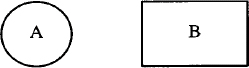
Fortunately, there is a simple way to deal with the problem presented in the last question. Lacking a reference object, you can create an invisible one using the invis attribute. This lets you specify a circle that is not drawn but still holds a place that you can reference.
.PS

down

ellipse

move down 1.25

circle radius .35 invis

move left li from left of last circle; box

move right li from right of last circle; box

arrow from lower left of last ellipse to top of 1st box

arrow from lower right of last ellipse to top of 2nd box

.PE
This pic description produces:
One thing that seems hard to get used to is that your current position always changes after an object is drawn, based on the motion in effect. This means you have to keep in mind the location of the starting point for the next object that you are going to draw.
You can use braces to enclose an object (or a series of objects or motions) so that the starting point is unchanged. In the last drawing, if the invis attribute didn’t solve the problem so easily, we could have used braces to maintain a central point below the ellipse from which you can move to draw the boxes. Here’s a different example that illustrates how braces can be used to control your position:
.PS

{arrow down}

{arrow up}

{arrow left}

arrow right

.PE
Each object, except the last, is enclosed in braces; all objects share the same starting point. This description produces:
Placing Text
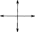
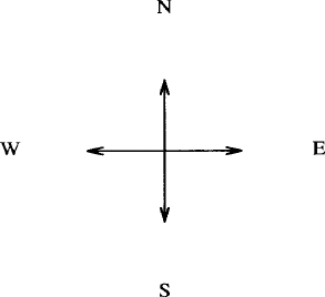
Text can be placed in a drawing just like an object. You have to take care in placing text, as in the next example, where we specify a move so that the compass points are not drawn on top of the arrowheads:
.PS

{arrow down; move; "S" }

{arrow up; move; "N" }

{arrow left; move; "W" }

{arrow right; move; "E" }

.PE
Notice that the attributes of direction cause the object to be drawn in that direction and establish a new motion for successive objects. This description produces:
As mentioned, pic does not really handle text, allowing troff to do the work. In some ways, this is unfortunate. The thing to remember is that pic does not know where the text begins or ends. (You can use the attributes ljust or rjust to have the text left justified—the first character is positioned at that point—or right justified—the last character is at that point. These attributes can also be used with text labels.)
The pic program does not keep track of the start and the end of a text object. It only knows a single point which is the point where troff centers the text. In other words, a text item does not cause a change in position. Two consecutive quoted items of text (not used as labels to another object) will overwrite one another. Objects are drawn without regard to where the text item is, as shown in the next example:
"Start"; line;arrow;line; "Finish"
This description produces:
![]()
This example can be improved by right justifying the first text item (“Start” rjust) and left justifying the last text item (“Finish” ljust). As you’ll notice, though, the picture starts at the margin, and the label is forced out where it doesn’t belong.
![]()
The location of the point that pic knows about is unchanged. Most of the time, you will have to use the move command before and after inserting text.
Because pic works better with objects than text, the invis attribute can be used to disguise the object behind the text, and give you a way to place text where you can point to it.
.PS

down

ellipse invis "DECISION?"

move down 1.25

circle rad .35 invis "Maybe"

move left li from left of last circle; box invis "Yes"

move right li from right of last circle; box invis "NO"

arrow from lower left of last ellipse to top of 1st box

arrow from lower right of last ellipse to top of 2nd box

line <-> from bottom of last ellipse to top of last circle

.PE
This description produces:
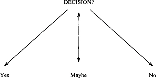
You may have recognized that the description for this drawing is basically the same one that produced the drawing at the beginning of this chapter. The invis attribute makes text labels, not objects, the subject of this picture. This should lead you to the idea that pic descriptions can be reused. Try to think of the form of a drawing separately from its content. Most drawings contain forms that can be reworked in the service of new material.
Place and Position Notation
Can you locate the starting points of the arrows on this ellipse?
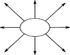
To write the description for this example is a test of patience and thoroughness, if nothing else. We start at the upper left of the ellipse and move clockwise around the ellipse.
.PS

ellipse

arrow up left from upper left of last ellipse

arrow up from top of last ellipse

arrow up right from upper right of last ellipse

arrow right from right of last ellipse

arrow right down from lower right of last ellipse

arrow down from bottom of last ellipse

arrow left down from lower left of last ellipse

arrow left from left of last ellipse

.PE
Although you can say upper left or lower left, you cannot say top left or bottom right.
Sometimes pic’s English-like input can get to be cumbersome. Fortunately, pic supports several different kinds of place and position notations that shorten descriptions.
You can reduce the phrase:
from bottom of last ellipse
to either of the following:
from .b of last ellipse
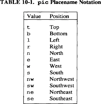
from last ellipse.b
You can use this notation for the primary points of any object. You can also refer to the compass points of an object, which provides a way to specify corners. Table 10-1 lists the placename notations.
Instead of writing:
from lower left of last ellipse
you might write:
from last ellipse.sw
Another simple way to shorten a description is to give an object its own name. The name must begin with an uppercase letter. If we assign the placename Elp to the ellipse:
Elp: ellipse
then we have either of the following ways to refer to specific points:
arrow up left from upper left of Elp

arrow up left from Elp.nw
Here’s the condensed version of the description for the previous example:
.PS

Elp: ellipse

arrow up left from Elp.nw

arrow up from Elp.n

arrow up right from Elp.ne

arrow right from Elp.e

arrow right down from Elp.se

arrow down from Elp.s

arrow left down from Elp.sw

arrow left from Elp.w

.PE
At least it helps to keep you from confusing the placement of the arrow with the drawing motion.
If you want to specify a point that is not at one of the compass points, you can indicate a point somewhere in between two places. You can use the following kind of construction:
of the way between first.position and second.position
or use the following notation:
The following example shows both forms:
box

arrow down left from 1/2 of the way between last box.sw \

and last box.w

arrow down right from 1/2 < last box.se, last box.e >
Although you may not want to intermix different forms for the sake of someone reading the description, pic does allow it. The preceding description produces:
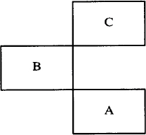
The at attribute can be used to position objects in a drawing.
box "A"; box with .se at last box.nw "B"

box with .sw at last box.ne "C"
This description produces:
The next example illustrates again the problem of placing text. This time we want to position callouts above and below the text.
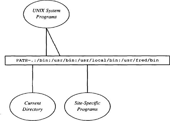
We position the text inside a long box. Because the callout lines will point to the box that surrounds the text rather than to the text itself, we try to specify approximately where to draw the lines.
.PS

      #    "#" introduces a comment

      #

      # Describe box; escape end of line to include

      # text on separate line

      #

Path: box ht .25 wid 4 \

"\f(CWPATH=.:/bin:/usr/bin:/usr/local/bin:/usr/fred/bin\fR"

      #

      # Describe line down from box and put top of ellipse

      # at end of last line; label will be printed

      # in 9-point italic.

      #

line down from 1/3 <Path.sw, Path.s>

ellipse "\fI\s9Current" "Directory\s0\fP" with .t at \

end of last line

      #

      # Describe two lines, one up from box

      # and a second down to the point right of it.

      #

line up from 1/2 <Path.nw, Path.n>

line to 2/3 <Path.nw, Path.n>

ellipse "\fI\s9UNIX System" "Programs\s0\fP" with .b at \

start of last line

      #

      # Describe the third callout below the box.

      #

line down from Path.s

ellipse "\fI\s9Site-Specific" "Programs\s0\fP" with .t at \

end of last line

.PE
Admittedly, positioning callouts is guesswork; it took several iterations to align the callouts with the appropriate text.
Defining Object Blocks
You can describe any sequence of motions or objects as a block. A block is defined between a pair of brackets ([]). You can also give the block a placename, beginning with an uppercase letter. Some of the objects that we have created in this chapter, such as a square, triangle, or compass, could be defined as blocks and named so that we can refer to each one as a single object.
Rtriangle: [

     linewid = 1

     line down then right then up left

     ]

.ps 18

.ft I

"1" at Rtriangle.w

"2" at Rtriangle.s

"3" at Rtriangle

.ft R

.ps 10
This description produces:
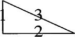
We are able to refer to the compass points of the block, although these points may not always be where you expect. The number 3 is printed at the center of Rtriangle according to pic. But in fact its position is the side opposite the right angle. The “center” of this block is at the center of a box that shares the bottom and left sides of the right triangle.
You can also refer to positions for a single block using brackets. The reference [].w is a position at the west end of the block.
In this example, instead of specifying individual line lengths, we redefined the variable linewid. This is the variable that pic accesses to determine how long a line should be. Shortly, we’ll look at all the variables preset by pic. Generally, what you describe within a block remains local to the block. Thus, linewid would not affect other lines outside the block. Otherwise, resetting a variable has an effect not only on other objects in that drawing but also on other drawings in that file.
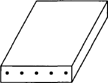
The best use of blocks in a drawing is to define significant portions so that you can position them accurately. Blocks usually relate to the content of a drawing. In the next example, we describe a two-dimensional box to represent a modem.
MOD: [

BOXA: box wid 1 ht .25 " \(bu   \(bu   \(bu   \(bu   \(bu "

line from BOXA.nw up 1 right .5 x

then right 1 then down 1 left .5 to BOXA.ne

line from BOXA.se up 1 right .5 then up .25

]
The block, named MOD, consists of a box followed by a series of lines. The box is given a name, BOXA. The special character sequence \ (bu represents a bullet (interpreted by troff, not pic). This description produces:
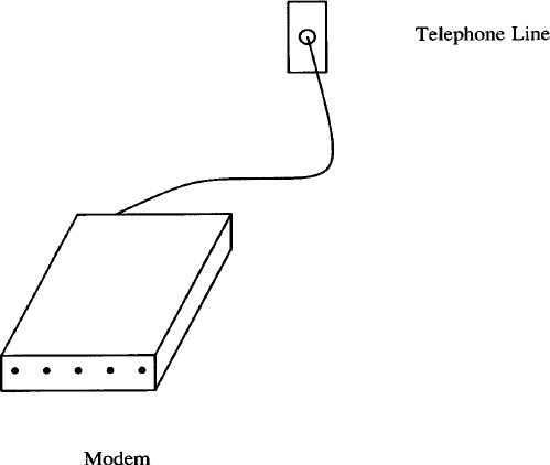
The next block, named WALL, describes a drawing of a telephone wall socket. It contains two objects, a box named BOXB and a circle inside the box named CIR.
WALL: [

BOXB: box wid .25 ht .5

CIR: circle at center of BOXB radius .05

]  with .s at MOD.ne + (.5,1)
To position this block in relation to MOD, we describe a position 1 inch up and .5 inch to the left of the top right-hand corner of MOD. Then we draw a spline from the modem to the wall socket. This introduces us to the fact that no matter how we specify an object, pic locates that object in a Cartesian coordinate system. We’ll look at this in more detail in a later section. For now, it is sufficent to note how we change position by adding or subtracting from the position on the x-axis and y-axis. MOD.ne+ (.5,1) adds .5 to the x-axis (moving to the right) and 1 to the y-axis (moving up) from the coordinates of MOD.ne.
Notice that we can refer to objects inside a block. If we had not named the circle, we could still refer to it as WALL.circle.
The last thing to do is to position the text:
move right 1 from WALL.e; " Telephone Line"

move down .5 from MOD.s "Modem"
This entire description produces the following drawing:
Resetting Standard Dimensions
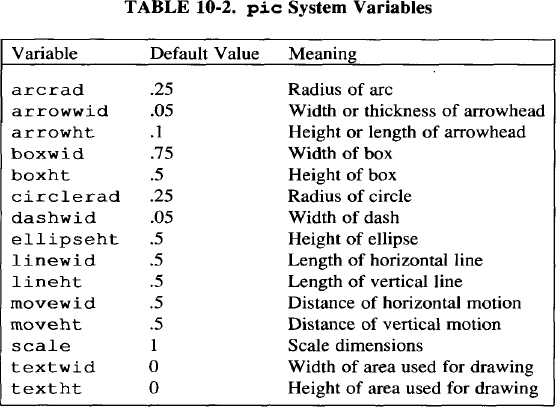
The pic program has a number of built-in variables that define the values used to draw standard pic objects.
Refer to Table 10-2. You can redefine these variables anywhere in a pic description. A variable set inside one pic description will remain in effect for other descriptions within the same file. One exception is a variable defined within a block; that definition is local to the block.
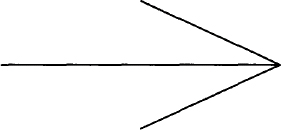
For instance, we can specify an oversize arrow by changing the following variables:
arrowwid = 1

arrowht = 1

linewid = 2

arrow
It produces the following pic drawing:
Controlling the Dimensions of a Drawing
The textwid and textht variables control the width and height respectively, of the area used by pic on a page. (It doesn’t refer to the amount of space occupied by an item of text.) These values can also be set as arguments to the .PS macro.
.PS width height
When you specify the width or height or both, pic scales the drawing to that size regardless of the absolute dimensions that are specified within the drawing. The only thing it doesn’t scale adequately is text. It can be easier to describe a drawing with simple units and have them scaled more precisely to fit on the page than to work with exact sizes.
A good example of scaling is turning the rounded box described previously in this chapter into a representation of a terminal screen.
.PS 2 4

line right 1; arc; line up ; arc

line left 1; arc; line down; arc

.PE
Although the pic description is made up of 1-inch lines, the actual screen produced by pic will be 4 inches wide and 2 inches high.
Normally, you want troff to output the regular lines of text on lines that follow the pic drawing. If the .PF (F for flyback) macro is used in place of .PE, troff will return to the position it held before the pic drawing was output. This feature is useful if we want to put formatted text within our large screen.
.PS 2 4

line right 1; arc; line up ; arc

line left 1; arc; line down; arc

.PE

.ft cw

.sp 2

Alcuin Development System     5/31/87

.SP

Please login:

.sp 6
This description produces:
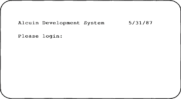
You have to remember to provide the space after the text to push the current position past the end of the screen. Otherwise subsequent text will also appear within the box.
Debugging pic Descriptions
You can invoke the pic preprocessor on its own to have it check through your file and report any syntax errors. This can save a lot of time, especially if your file contains other text that will be sent to troff, assuming that you wouldn?t want the file processed unless the pic descriptions succeeded. If you have the file circles, for example, that contains a pic description, you can invoke pic as:
$ pic circles
If processing is successful, pic output will stream past on your terminal screen. If pic finds an error in your description, it will print the error message.
If you have several pic descriptions in a file, or you have regular text surrounding a pic description, you can send the output to /dev/null, and only the error messages will be displayed on your screen.
You may want to invoke pic on its own simply to look at the output pic produces. For a discussion of the output that pic sends to troff, read about line drawing in Chapter 14.
▪ From Describing to Programming Drawings ▪
As we look at more advanced examples of pic, you may begin to question the amount of description that is required to produce a drawing. You may be amazed that drawings that look so simple require so many words. After you realize that you are approaching the limits of what can be described using an English-like syntax, you may want to look at pic from another perspective. You can view pic as a programming language for generating graphics.
Looking at this other side of pic, you will find that the descriptions are perhaps more difficult to read but much easier to write. The purpose of a “programmed” pic description is not to imitate a verbal description, but to minimize user input, to provide structures that can be used to produce several kinds of drawings, and to make it easier to change a drawing.
The focus of the rest of this chapter will be to introduce many of these special features of pic, including variables, expressions, and macros. But there are more possibilities than we can attempt to describe. The pic program follows the general UNIX philosophy that any program should be able to accept input from any program and direct its output to another program, troff. Thus, pic descriptions can be built by other UNIX utilities. For instance, you might develop an awk program specifically designed for creating flow charts.
Locating Objects Using Cartesian Coordinates
For more exact positioning of objects and text, pic uses a standard Cartesian coordinate system. The first object drawn, including a move, starts at position 0,0. The x and y position of a circle, an ellipse, or a box is at the center of the object. For lines, this position refers to the beginning. For arcs, this position is at the center point of the related circle. You can position objects using the at attribute:
circle "0,0" at 0,0

circle "1,1" at 1,1

circle "1,0" at 1,0

circle "2,1" at 2,1
This description produces:
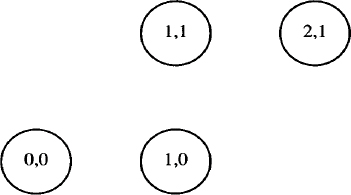
The center of the circle is placed at the specified coordinates. You could also write:
circle with .t at 1,1
and it would place the top of the circle at that position. A reference to last circle would still locate the center of the circle, but a line drawn from 1,1 would begin at the top of the circle.
Note that the position of 0,0 will not always be the same place on the page. The first object drawn is the point of reference; movement to the left of that point will cause 0,0 to be moved over towards the center of the page.
box ht 0.3 wid 0.3 "0,0"

move to 1,0

box "1,0" same

move to -1,0

box "-1,0" same
This description produces:
![]()
It may be helpful to sketch a drawing on graph paper and then translate it into a pic description. Standard graph paper is divided into quarter-inch squares. When you use graph paper, you might find it useful to set the scale variable to 4. All dimensions and positions will be divided by the value of scale, which is 1 by default.
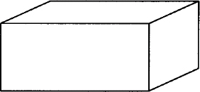
It is much easier to describe a drawing in full units rather than fractions. Look at the following description:
scale=4

line from 0,0 to 0,3 then to 6,3 then to 6,0 then to 0,0

line from 6,0 to 8,1 then to 8,4 then to 2,4 then to 0,3

line from 6,3 to 8,4
The distance between 0 and 1 is normally 1 inch. Because we are scaling this drawing by 4, the actual distance is ¼ inch. It seems easier to describe a point as 2,3 rather than 5,.75. This description produces a two-dimensional box:
Although pic scales the location of text, it is your responsibility to reduce the size of the text to fit a scaled object. You can also use scale to change the basic unit of measurement from inches to any other unit. For instance, setting scale to 6 will cause all dimensions and coordinates to be interpreted in picas (6 picas to the inch).
Splines and arcs are much easier to draw using coordinates. In the following example, we use a spline to draw a smooth curve between several points on a crude graph.
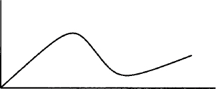
This graph is produced by the following description:
scale=4

line from 0.0 to 0,4

line from 0,0 to 9,0

spline from 0,0 to 3,3 then to 5,.25 then to 8,1.5
You can also specify relative coordinates as an expression within parentheses. It has the effect of adding or subtracting from the absolute coordinates of a particular place.
The same attribute allows us to duplicate the size of a previous object. The expression circle same means “the same size as the last circle.” This description produces:
Similarly, you can achieve finer control over positioning by moving from a compass point:
box with .sw at last box.ne+(.05,-.05)
Expressions and User-Defined Variables
An expression can be used to supply the dimensions or the position of an object. Any of the following operators can be used in an expression: +, –, *, /, and % (modulo).” Expressions can be used to manipulate the built-in variables as follows:
circle rad circlerad/2
This will draw a circle with a radius that is half the size of the default radius. An expression can also refer to the value of placenames. The coordinates of any object can be specified as .x and .y. Here’s a list of some of the possibilities:
BoxA.x The x-coordinate of the center of BoxAlast box.y The y-coordinate of the center of the last boxBoxA.s.y The y-coordinate of the southern compass point of BoxABoxA.wid The width of BoxAlast circle.rad The radius of the last circle
The next description defines a box and then divides the specified height and width of that box to produce a second box half that size.
Boxa: box ht 2 wid 3; arrow

box ht Boxa.ht/2 wid Boxa.wid/2
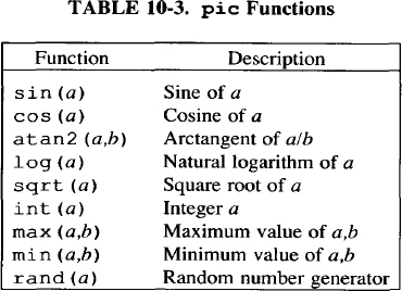
The pic program also has a number of functions that can be evaluated in an expression, as shown in Table 10-3:
In giving the size or length of an object, you can name and define your own variables. A variable is any lowercase name that is not reserved as part of the pic language. A variable can be defined as a constant or an expression.
a=ellipsewid*3

b=ellipseht/2

ellipse wid a ht b
This description produces:
![]()
Defining Macros
With macros, you can predefine a series of objects or motions that will be included in the description each time you refer to the macro by name.
define name %definition
%
A percent sign (%) is used here as the delimiter but any character not in the definition can be used. The format of the define statement is shown on three lines for readability only; a simple macro could be put on a single line. The definition can extend across as many lines as necessary.
When you refer to name in your description, The pic program will replace it with the definition.
Macros can also take arguments. These arguments are specified in the definition as $1 thru $9. They will be replaced by the arguments supplied when the macro is invoked.
A macro does not exist as a place or position as far as pic is concerned. The pic program simply replaces the macro name with the lines defined in the macro. You cannot refer to the macro as you would refer to a block. However, you can set positions from within a macro.
in the following example, the “tail” hanging down from the box and the list of items drawn to the right of it were produced by a macro.
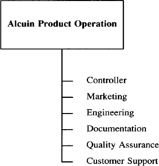
In the pic description that produced this drawing, the box is drawn explicitly and a short line is started down from the bottom of the box. Then a macro named dept is invoked to produce each item on the list.
define dept %

             line down .25

           { line right .15; move right .2; "$1" ljust }

           %
in this macro, after a line down is described, the rest of the description is put within braces to reserve the starting position for the next macro call. A short line is drawn, followed by a move to place the text in the correct position. Quotation marks are placed around the argument because the argument will contain a text label.
This macro is invoked for the first item as:
dept(Controller)
Controller is supplied as the first argument, which the macro inserts as a text object. Notice that the argument in the definition is quoted (“$1”) so that the actual text when specified does not have to be quoted.
The previous drawing was modeled after an example shown in Estimating Illustration Costs: A Guide published by the Society for Technical Communication. The guide considered this drawing to be of medium difficulty and estimated that it would require an hour of an illustrator’s time. It took ten to fifteen minutes to design and execute this description for pic, including correcting some syntax errors and formatting for the laser printer. Here’s the complete description of the drawing:
.PS

box ht .75 wid 1.75 "Alcuin Product Operation"

line down .25 from bottom of last box

define dept %

             line down .25

           { line right .15; move right .2; "$1" ljust }

           %

dept (Controller)

dept(Marketing)

dept (Engineering)

dept (Documentation)

dept(Quality Assurance)

dept(Customer Support)

.PE
The second example of macro use is probably harder to read than it is to write. Let’s look at it in portions. The purpose of the drawing is to represent a network of computers. We decided to use three types of objects to represent each type of computer: a square, a triangle, and small circle. These objects will appear in a hierarchy and lines will be drawn to connect an object on one level with an object on the level below it. Before starting to describe it in pic terms, we prepared a rough sketch of the drawing on graph paper. This made us realize that we could easily determine the coordinate points of objects; thus, all the macros are set up to accept coordinate positions.
Comments, beginning with #, describe the user-supplied arguments. Following are the definitions for three macros: backbone (a box), local (a triangle), and endpt (a small circle).
scale = 4

top = 10

define backbone %

          # $1 = x coordinate ; $2 = label

          ycoord = top-2

          BB$1: box wid 1 ht 1 with .sw at $1,ycoord

          "$2" at ($1,ycoord)+(2,1) ljust

          %

define local %

          # $1 = x coordinate; $2 = label

          ycoord = top-5

          LO$1: move to $1,ycoord

          line down l left 1 then right 2 then up 1 left 1
          "$2" at ($1,ycoord)-(0,.7)

          %

define endpt %

         # $1 = x coordinate

         ycoord = top-8

         circle rad .125 with .n at $1,ycoord

         EP$1: last circle.n
          %
Because each type of object maintained the same height (or position on the y-axis), a variable ycoord was set up to supply that position from the top of the drawing. (The top of the drawing is defined by another variable.)
Each of these macros requires that you supply an x-axis coordinate as the first argument. This argument is also used to assign a unique placename that is used later when we draw lines between objects.
The backbone and local macros also take a second argument for a label. Handling text inside a macro definition is especially convenient if you are going to change the font and point size.
The next task is to connect the backbone systems to the local systems and the local systems to endpoints. Although we know which types of objects are connected, not all objects are connected in the same way. We decided that the macros require two arguments to supply the x-coordinate for each of the two objects.
define BtoL %

            # $1 = x coord of backbone; $2 = x coord of

            # local

            line from BB$1-(O,.5) to LO$2

            %

define LtoE %

            # $1 = x coord of local; $2 = x coord of endpt

            line from L0$1-(0,1) to EP$2

            %
The BtoL and LtoE macros draw lines between the placenames set up by the backbone, local, and endpt macros.
Here are the actual macro calls:
backbone(10,IBM/370)

backbone(18,DEC VAX)

local(8,68K-1)

local(13,68K-2)

local(17,68K-3)

endpt(7)

endpt(9)

endpt(12)

endpt(13)

endpt(14)

endpt(16)

endpt(18)
BtoL(10,8)

BtoL(10,13)

BtoL(18,17)

LtoE(8,7); LtoE(8,9)

LtoE(13,12); LtoE(13,13); LtoE(13,14)

LtoE(17,16); LtoE(17,18)

linefrom LO13 to LO17

"\s8Personal Computers\s0" at 13,1

"\s12\fBA Network of Computers\sO\fR" ljust at 10,top
Notice that arguments supplied to a macro are separated by commas and that an argument may contain a space. Here’s what the description produces:
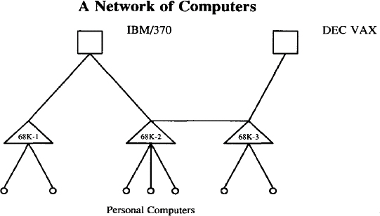
Twelve objects are specified and eleven lines are drawn between the objects. One line is explicitly drawn connecting the second triangle to the third triangle. It didn’t make sense to define a macro for this single instance. But if you were setting this up for others to use, such a macro would be necessary.
Shortly, we will be looking at several relatively new features that make pic even more powerful for generating pictures. In particular, these features allow us to improve our effort to generate a diagram of a computer network.
pic’s Copy Facility
The pic program provides an interesting copy facility that has two different uses: it allows you to read a pic description from a remote file, and it allows you to read lines of data and pass them as individual arguments to a macro.
If you are going to use pic regularly, you should think about maintaining a macro library. You might define frequently used objects, such as triangles, and place them in their own file. You can include the file in your description with the following line:
copy "usr/lib/macros/pic/triangles"
Putting the filename in double quotation marks is required. Any .PS/.PE macros that are found in the remote file are ignored.
You might also define a set of related macros for a particular type of drawing, such as an organizational chart or a flow diagram. After you have taken the time to create and test a description, you should consider structuring it so that the forms can be easily used in other drawings.
This copy facility replaces an older construct that allowed you to redirect input from another file through the .PS macro.
.PS < triangles
A second use of the copy facility is to read data through a macro. We’ll show how the endpt macro from our last example can be designed to use this facility. In a file where we had already defined a macro named endpt, we could invoke this macro with the following command:
copy thru endpt

7

9

12

13

14

16

18
The pic program reads each line of data up to the .PE and replaces each argument in the macro definition with the corresponding field from each line. In this example, the macro is executed seven times, once for each line of data.
We could put the data in a separate file, named endpt.d, for example. Then you enter this version of the copy command:
copy "endpt.d" thru endpt
The double quotation marks are required. Now the endpt macro will be executed for each line in the file endpt.d. (The filename suffix .d is optional and signifies that the file contains data for a macro call.)
You can specify a string that pic will recognize in the remote file as a signal to stop reading input. Used with copy thru, until is followed by the string. In the following example, the word STOP is used as the string:
copy "endpt.d" thru endpt until STOP
You can also use until when you are taking input from the same file:
In both cases, pic will read lines of data until it comes across the string STOP.
Another way to use copy thru is to supply the macro definition. This is a compact, single-step method:
copy "endpt.d" thru %

         # $1 = x coordinate

         ycoord = top-8

         circle rad .125 with .n at $1,ycoord

         EP$1: last circle.n

                    %
Although the percent sign is used as the delimiter, any character not found in the definition could be used. The copy thru statement with the macro definition can be put on a single line, which is helpful for short definitions.
copy thru % box at $1,$2 %

1 1

1 2

1 3

1 4
Because you can get a description down to this level, basically consisting of functions, you could have a standard description file associated with independent data files. You could write a program to build the data files from user input or from some other source.
Executing UNIX Commands
You can execute any UNIX command from pic, using the following syntax:
sh % command %
Again, the percent sign represents any valid delimiter character. The pic program submits this command to the shell for execution and then returns to interpret the next line of the description. You could issue a command to obtain data from another file:
sh % awk -F: {print$1} /etc/passwd %
▪ pic Enhancements ▪
Most of the enhancements found in new versions of pic are aimed at developing pic as a graphics programming language. Additional capabilities include for loops and if conditional statements. A for loop allows one or more pic commands to be executed as long as a condition is met.
Each time through the loop the value of the variable i is incremented by .05, producing five boxes of increasing height. The by clause specifies the amount that the variable is incremented each time through the loop. If the by clause is omitted, then the variable is incremented by 1. The % is used as the delimiter marking the commands to be executed on each pass.
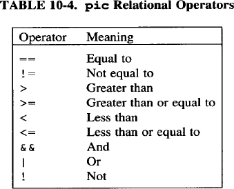
The if statement evaluates an expression to determine if it is true or false. If true, then specified pic commands are executed. If false, the then clause is not acted upon; instead, an else clause, if specified, is read and commands specified inside it are executed.
if x > y then % x = y % else % x = x + 1%
This conditional statement evaluates the expression x > y. If true, x is set to y; if false, the value of x is incremented by 1. The % is a delimiter marking the beginning and end of the commands specified for both then and else clauses. The expression inside an if statement can use any of the relational operators that are shown in Table 10-4.
In addition to enhancements that add more graphics programming features to pic, progress has been made in allowing input to be taken from bit-mapped graphic terminals and translated into pic output. A separate program called cip, available on some systems, allows users to create drawings using a mouse (a la MacDraw for the Macintosh). The cip program generates a pic description of a drawing that can be included in any file to be processed by troff.
Get UNIX° TEXT PROCESSING now with the O’Reilly learning platform.
O’Reilly members experience books, live events, courses curated by job role, and more from O’Reilly and nearly 200 top publishers.

