Chapter 1
Reminders and General Points
1.1. Lines
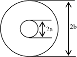
We use the term “line” to refer to all systems of two conductors capable of propagating a high-frequency signal. There are two types of line theorized: the bifilar line, formed of two parallel conductors, and the coaxial line. The microstrip line is connected to one or the other depending on the problem to be solved. The waveguide, which is a high-pass device (whereas lines are low-pass), can be considered as the transition between the line and the free propagation.
1.1.1. Bifilar lines
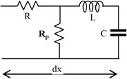
Figure 1.1.

Figure 1.2.

We use these lines little in the industry because they radiate a lot. Their practical application is limited to the fabrication of FM antennas, for example, where this characteristic becomes an advantage. From a theoretical point of view, on the other hand, it is the model we use in lessons to teach the Telegraphists’ equation and the rest of the theory. The line is the typical example of a circuit with distributed constants. Each element of length dx is electrically characterized by four basic quantities, a serial resistance dR = R.dx, a parallel resistance dRp = Rp.dx, a serial inductance dL = Ldx and a parallel capacitance dC = Cdx. Since it is a low-pass structure, a HF line possesses a high cut-off frequency.
Telegraphists’ ...
Get VHF / UHF Filters and Multicouplers: Application of Air Resonators now with the O’Reilly learning platform.
O’Reilly members experience books, live events, courses curated by job role, and more from O’Reilly and nearly 200 top publishers.

