18.8 DESIGN 3: DESIGN SPACE EXPLORATION WHEN s3 = [1 −0.5]
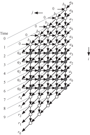
Figure 18.6 shows the DAG for the polynomial division algorithm based on our timing function choice s3. We note from the figure that all signals are now pipelined, as indicated by the arrows connecting the nodes. However, we note that there are nodes that do not lie on any equitemporal planes. We have several choices for the timing of nodes that lie between two temporal planes. Alternatively, we could assign a time value equal to either of the temporal planes surrounding the node. In addition, we could assign this node to operate on the negative edge of the clock. The former choice leads to nodes that do not have registers. The latter choice leads to nodes that have registers triggered by the negative edge of the clock. This is the option we follow here.
Figure 18.6 DAG for polynomial division algorithm when s3 = [1 −0.5], n = 9, and m = 5.

Similar to the two previous designs, we choose a projection vector given by
(18.40)
![]()
The corresponding projection matrix P3 is given by
(18.41)
![]()
A point in the DAG given by the coordinates p = [i j]t will be mapped by the projection matrix P3 into the point = P3p. The corresponding ...
Get Algorithms and Parallel Computing now with the O’Reilly learning platform.
O’Reilly members experience books, live events, courses curated by job role, and more from O’Reilly and nearly 200 top publishers.

