Chapter 1. Getting Started
1.0. Introduction
The Arduino environment has been designed to be easy to use for beginners who have no software or electronics experience. With Arduino, you can build objects that can respond to and/or control light, sound, touch, and movement. Arduino has been used to create an amazing variety of things, including musical instruments, robots, light sculptures, games, interactive furniture, and even interactive clothing.
Note
If you’re not a beginner, please feel free to skip ahead to recipes that interest you.
Arduino is used in many educational programs around the world, particularly by designers and artists who want to easily create prototypes but do not need a deep understanding of the technical details behind their creations. Because it is designed to be used by nontechnical people, the software includes plenty of example code to demonstrate how to use the Arduino board’s various facilities.
Though it is easy to use, Arduino’s underlying hardware works at the same level of sophistication that engineers employ to build embedded devices. People already working with microcontrollers are also attracted to Arduino because of its agile development capabilities and its facility for quick implementation of ideas.
Arduino is best known for its hardware, but you also need software to program that hardware. Both the hardware and the software are called “Arduino.” The combination enables you to create projects that sense and control the physical world. The software is free, open source, and cross-platform. The boards are inexpensive to buy, or you can build your own (the hardware designs are also open source). In addition, there is an active and supportive Arduino community that is accessible worldwide through the Arduino forums and the wiki (known as the Arduino Playground). The forums and the wiki offer project development examples and solutions to problems that can provide inspiration and assistance as you pursue your own projects.
The recipes in this chapter will get you started by explaining how to set up the development environment and how to compile and run an example sketch.
Note
Source code containing computer instructions for controlling Arduino functionality is usually referred to as a sketch in the Arduino community. The word sketch will be used throughout this book to refer to Arduino program code.
The Blink sketch, which comes with Arduino, is used as an example for recipes in this chapter, though the last recipe in the chapter goes further by adding sound and collecting input through some additional hardware, not just blinking the light built into the board. Chapter 2 covers how to structure a sketch for Arduino and provides an introduction to programming.
Note
If you already know your way around Arduino basics, feel free to jump forward to later chapters. If you’re a first-time Arduino user, patience in these early recipes will pay off with smoother results later.
Arduino Software
Software programs, called sketches, are created on a computer using the Arduino integrated development environment (IDE). The IDE enables you to write and edit code and convert this code into instructions that Arduino hardware understands. The IDE also transfers those instructions to the Arduino board (a process called uploading).
Arduino Hardware
The Arduino board is where the code you write is executed. The board can only control and respond to electricity, so specific components are attached to it to enable it to interact with the real world. These components can be sensors, which convert some aspect of the physical world to electricity so that the board can sense it, or actuators, which get electricity from the board and convert it into something that changes the world. Examples of sensors include switches, accelerometers, and ultrasound distance sensors. Actuators are things like lights and LEDs, speakers, motors, and displays.
There are a variety of official boards that you can use with Arduino software and a wide range of Arduino-compatible boards produced by members of the community.
The most popular boards contain a USB connector that is used to provide power and connectivity for uploading your software onto the board. Figure 1-1 shows a basic board that most people start with, the Arduino Uno.
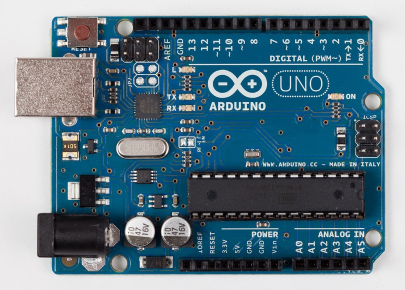
The Arduino Uno has a second microcontroller onboard to handle all USB communication; the small surface-mount chip (the ATmega8U2) is located near the USB socket on the board. This can be programmed separately to enable the board to appear as different USB devices (see Recipe 18.14 for an example). The Arduino Leonardo board replaces the ATmega8U2 and the ATmega328 controllers with a single ATmega32u4 chip that implements the USB protocol in software. The Arduino-compatible Teensy and Teensy+ boards from PJRC (http://www.pjrc.com/teensy/) are also capable of emulating USB devices. Older boards, and most of the Arduino-compatible boards, use a chip from the FTDI company that provides a hardware USB solution for connection to the serial port of your computer.
You can get boards as small as a postage stamp, such as the Arduino Mini and Pro Mini; larger boards that have more connection options and more powerful processors, such as the Arduino Mega; and boards tailored for specific applications, such as the LilyPad for wearable applications, the Fio for wireless projects, and the Arduino Pro for embedded applications (standalone projects that are often battery-operated).
Recent additions to the range include the Arduino ADK, which has a USB host socket on it and is compatible with the Android Open Accessory Development Kit, the officially approved method of attaching hardware to Android devices. The Leonardo board uses a controller chip (the ATmega32u4) that is able to present itself as various HID devices. The Ethernet board includes Ethernet connectivity, and has a Power Over Ethernet option, so it is possible to use a single cable to connect and power the board.
Other Arduino-compatible boards are also available, including the following:
Arduino Nano, a tiny board with USB capability, from Gravitech (http://store.gravitech.us/arna30wiatn.html)
Bare Bones Board, a low-cost board available with or without USB capability, from Modern Device (http://www.moderndevice.com/products/bbb-kit)
Boarduino, a low-cost breadboard-compatible board, from Adafruit Industries (http://www.adafruit.com/)
Seeeduino, a flexible variation of the standard USB board, from Seeed Studio Bazaar (http://www.seeedstudio.com/)
Teensy and Teensy++, tiny but extremely versatile boards, from PJRC (http://www.pjrc.com/teensy/)
A list of Arduino-compatible boards is available at http://www.freeduino.org/.
See Also
An overview of Arduino boards: http://www.arduino.cc/en/Main/Hardware.
Online guides for getting started with Arduino are available at http://arduino.cc/en/Guide/Windows for Windows, http://arduino.cc/en/Guide/MacOSX for Mac OS X, and http://www.arduino.cc/playground/Learning/Linux for Linux.
A list of over a hundred boards that can be used with the Arduino development environment can be found at: http://jmsarduino.blogspot.com/2009/03/comprehensive-arduino-compatible.html
1.1. Installing the Integrated Development Environment (IDE)
Solution
The Arduino software for Windows, Mac, and Linux can be downloaded from http://arduino.cc/en/Main/Software.
The Windows download is a ZIP file. Unzip the file to any convenient directory—Program Files/Arduino is a sensible place.
Note
A free utility for unzipping files, called 7-Zip, can be downloaded from http://www.7-zip.org/.
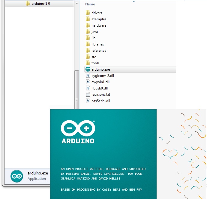
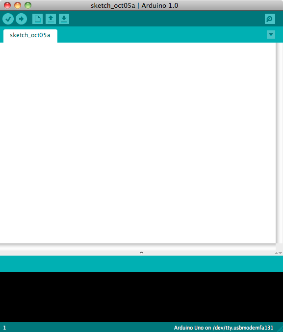
Unzipping the file will create a folder named Arduino-00<nn> (where <nn> is the version number of the Arduino release you downloaded). The directory contains the executable file (named Arduino.exe), along with various other files and folders. Double-click the Arduino.exe file and the splash screen should appear (see Figure 1-2), followed by the main program window (see Figure 1-3). Be patient, as it can take some time for the software to load.
The Arduino download for the Mac is a disk image (.dmg); double-click the file when the download is complete. The image will mount (it will appear like a memory stick on the desktop). Inside the disk image is the Arduino application. Copy this to somewhere convenient—the Applications folder is a sensible place. Double-click the application once you have copied it over (it is not a good idea to run it from the disk image). The splash screen will appear, followed by the main program window.
Linux installation varies depending on the Linux distribution you are using. See the Arduino wiki for information (http://www.arduino.cc/playground/Learning/Linux).
To enable the Arduino development environment to communicate with the board, you need to install drivers.
On Windows, use the USB cable to connect your PC and the Arduino
board and wait for the Found New Hardware Wizard to appear. If you are using an
Uno board, let the wizard attempt to find and install
drivers. It will fail to do this (don’t worry, this is the expected
behavior). To fix it you now need to go to Start Menu→Control Panel→System and Security. Click on System, and
then open Device Manager. In the listing that is displayed find the
entry in COM and LPT named Arduino UNO (COM
nn). nn will be the
number Windows has assigned to the port created for the board. You
will see a warning logo next to this because the appropriate drivers
have not yet been assigned. Right click on the entry and select Update
Driver Software. Choose the “Browse my computer for driver software”
option, and navigate to the Drivers folder inside the Arduino folder
you just unzipped. Select the ArduinoUNO.inf file and windows should then
complete the installation process.
If you are using an earlier board (any board that uses FTDI drivers) with Windows Vista or Windows 7 and are online, you can let the wizard search for drivers and they will install automatically. On Windows XP (or if you don’t have Internet access), you should specify the location of the drivers. Use the file selector to navigate to the FTDI USB Drivers directory, located in the directory where you unzipped the Arduino files. When this driver has installed, the Found New Hardware Wizard will appear again, saying a new serial port has been found. Follow the same process as before.
Note
It is important that you go through the sequence of steps to install the drivers two times, or the software will not be able to communicate with the board.
On the Mac, the latest Arduino boards, such as the Uno, can be used without additional drivers. When you first plug the board in a notification will pop up saying a new network port has been found, you can dismiss this. If you are using earlier boards (boards that need FTDI drivers), you will need to install driver software. There is a package named FTDIUSBSerialDriver, with a range of numbers after it, inside the disk image. Double-click this and the installer will take you through the process. You will need to know an administrator password to complete the process.
On Linux, most distributions have the driver already installed, but follow the Linux link given in this chapter’s introduction for specific information for your distribution.
Discussion
If the software fails to start, check the troubleshooting section of the Arduino website, http://arduino.cc/en/Guide/Troubleshooting, for help solving installation problems.
See Also
Online guides for getting started with Arduino are available at http://arduino.cc/en/Guide/Windows for Windows, http://arduino.cc/en/Guide/MacOSX for Mac OS X, and http://www.arduino.cc/playground/Learning/Linux for Linux.
1.2. Setting Up the Arduino Board
Solution
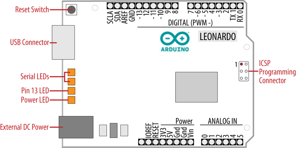
Plug the board in to a USB port on your computer and check that the green LED power indicator on the board illuminates. Standard Arduino boards (Uno, Duemilanove, and Mega) have a green LED power indicator located near the reset switch.
An orange LED near the center of the board (labeled “Pin 13 LED” in Figure 1-4) should flash on and off when the board is powered up (boards come from the factory preloaded with software to flash the LED as a simple check that the board is working).
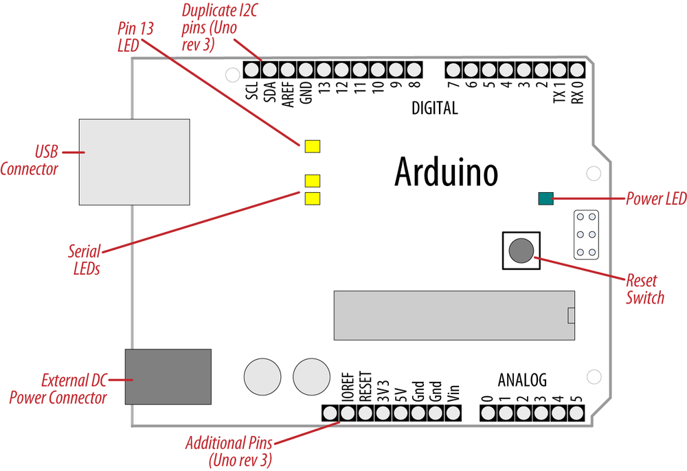
New boards such as Leonardo have the LEDs located near the USB connector; see Figure 1-5. Recent boards have duplicate pins for use with I2C (marked
SCL and SDA). These boards also have a pin
marked IOREF that can be
used to determine the operating voltage of the chip.
Note
The latest boards have three additional connections in the new standard for connector layout on the board. This does not affect the use of older shields (they will all continue to work with the new boards, just as they did with earlier boards). The new connections provide a pin (IOREF) for shields to detect the analog reference voltage (so that analog input values can be calibrated to the supply voltage), SCL and SDA pins to enable a consistent connection for I2C devices (the location of the I2C pins has differed on previous boards due to different chip configurations). Shields designed for the new layout should work on any board that uses the new pin locations. An additional pin (next to the IOREF pin) is not being used at the moment, but enables new functionality to be implemented in the future without needing to change the pin layout again.
Discussion
If the power LED does not illuminate when the board is connected to your computer, the board is probably not receiving power.
The flashing LED (connected to digital output pin 13) is being controlled by code running on the board (new boards are preloaded with the Blink example sketch). If the pin 13 LED is flashing, the sketch is running correctly, which means the chip on the board is working. If the green power LED is on but the pin 13 LED is not flashing, it could be that the factory code is not on the chip; follow the instructions in Recipe 1.3 to load the Blink sketch onto the board to verify that the board is working. If you are not using a standard board, it may not have a built-in LED on pin 13, so check the documentation for details of your board. The Leonardo board fades the LED up and down (it looks like the LED is “breathing”) to show that the board is working.
See Also
Online guides for getting started with Arduino are available at http://arduino.cc/en/Guide/Windows for Windows, http://arduino.cc/en/Guide/MacOSX for Mac OS X, and http://www.arduino.cc/playground/Learning/Linux for Linux.
A troubleshooting guide can be found at http://arduino.cc/en/Guide/Troubleshooting.
1.3. Using the Integrated Development Environment (IDE) to Prepare an Arduino Sketch
Solution
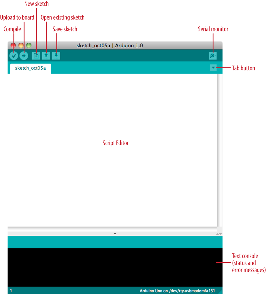
Use the Arduino IDE to create, open, and modify sketches that define what the board will do. You can use buttons along the top of the IDE to perform these actions (shown in Figure 1-6), or you can use the menus or keyboard shortcuts (shown in Figure 1-7).
The Sketch Editor area is where you view and edit code for a sketch. It supports common text-editing keys such as Ctrl-F (⌘+F on a Mac) for find, Ctrl-Z (⌘+Z on a Mac) for undo, Ctrl-C (⌘+C on a Mac) to copy highlighted text, and Ctrl-V (⌘+V on a Mac) to paste highlighted text.
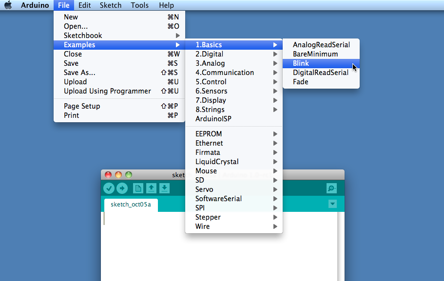
Figure 1-7 shows how to load the Blink sketch (the sketch that comes preloaded on a new Arduino board).
After you’ve started the IDE, go to the File→Examples menu and select 1. Basics→Blink, as shown in Figure 1-7. The code for blinking the built-in LED will be displayed in the Sketch Editor window (refer to Figure 1-6).
Before the code can be sent to the board, it needs to be converted into instructions that can be read and executed by the Arduino controller chip; this is called compiling. To do this, click the compile button (the top-left button with a tick inside), or select Sketch→Verify/Compile (Ctrl-R; ⌘+R on a Mac).
You should see a message that reads “Compiling sketch...” and a progress bar in the message area below the text-editing window. After a second or two, a message that reads “Done Compiling” will appear. The black console area will contain the following additional message:
Binary sketch size: 1026 bytes (of a 32256 byte maximum)
The exact message may differ depending on your board and Arduino version; it is telling you the size of the sketch and the maximum size that your board can accept.
Discussion
Source code for Arduino is called a sketch. The process that takes a sketch and converts it into a form that will work on the board is called compilation. The IDE uses a number of command-line tools behind the scenes to compile a sketch. For more information on this, see Recipe 17.1.
The final message telling you the size of the sketch indicates how much program space is needed to store the controller instructions on the board. If the size of the compiled sketch is greater than the available memory on the board, the following error message is displayed:
Sketch too big; see http://www.arduino.cc/en/Guide/Troubleshooting#size
 for tips on reducing it.
If this happens, you need to make your sketch smaller to be able to put it on the board, or get a board with higher capacity.
If there are errors in the code, the compiler will print one or more error messages in the console window. These messages can help identify the error—see Appendix D on software errors for troubleshooting tips.
Note
To prevent accidental overwriting of the examples, the Arduino IDE does not allow you to save changes to the provided example sketches. You must rename them using the Save As menu option. You can save sketches you write yourself with the Save button (see Recipe 1.5).
As you develop and modify a sketch, you should also consider using the File→Save As menu option and using a different name or version number regularly so that as you implement each bit, you can go back to an older version if you need to.
Note
Code uploaded onto the board cannot be downloaded back onto your computer. Make sure you save your sketch code on your computer. You cannot save changes back to the example files; you need to use Save As and give the changed file another name.
See Also
Recipe 1.5 shows an example sketch. Appendix D has tips on troubleshooting software problems.
1.4. Uploading and Running the Blink Sketch
Solution
Connect your Arduino board to your computer using the USB cable. Load the Blink sketch into the IDE as described in Recipe 1.3.
Next, select Tools→Board from the drop-down menu and select the name of the board you have connected (if it is the standard Uno board, it is probably the first entry in the board list).
Now select Tools→Serial Port. You will get a drop-down list of available serial ports on your computer. Each machine will have a different combination of serial ports, depending on what other devices you have used with your computer.
On Windows, they will be listed as numbered COM entries. If there is only one entry, select it. If there are multiple entries, your board will probably be the last entry.
On the Mac, your board will be listed twice if it is an Uno board:
/dev/tty.usbmodem-XXXXXXX/dev/cu.usbmodem-XXXXXXX
If you have an older board, it will be listed as follows:
/dev/tty.usbserial-XXXXXXX/dev/cu.usbserial-XXXXXXX
Each board will have different values for
XXXXXXX. Select either entry.
Click on the upload button (in Figure 1-6, it’s the second button from the left), or choose File→Upload to I/O board (Ctrl-U, ⌘+U on a Mac).
The software will compile the code, as in Recipe 1.3. After the software is compiled, it is uploaded to the board. If you look at your board, you will see the LED stop flashing, and two lights (labeled as Serial LEDs in Figure 1-4) just below the previously flashing LED should flicker for a couple of seconds as the code uploads. The original light should then start flashing again as the code runs.
Discussion
For the IDE to send the compiled code to the board, the board needs to be plugged in to the computer, and you need to tell the IDE which board and serial port you are using.
When an upload starts, whatever sketch is running on the board is stopped (if you were running the Blink sketch, the LED will stop flashing). The new sketch is uploaded to the board, replacing the previous sketch. The new sketch will start running when the upload has successfully completed.
Note
Older Arduino boards and some compatibles do not automatically interrupt the running sketch to initiate upload. In this case, you need to press the Reset button on the board just after the software reports that it is done compiling (when you see the message about the size of the sketch). It may take a few attempts to get the timing right between the end of the compilation and pressing the Reset button.
The IDE will display an error message if the upload is not successful. Problems are usually due to the wrong board or serial port being selected or the board not being plugged in. The currently selected board and serial port are displayed in the status bar at the bottom of the Arduino window
If you have trouble identifying the correct port on Windows, try unplugging the board and then selecting Tools→Serial Port to see which COM port is no longer on the display list. Another approach is to select the ports, one by one, until you see the lights on the board flicker to indicate that the code is uploading.
See Also
The Arduino troubleshooting page: http://www.arduino.cc/en/Guide/Troubleshooting.
1.5. Creating and Saving a Sketch
Solution
To open an editor window ready for a new sketch, launch the IDE (see Recipe 1.3), go to the File menu, and select New. Paste the following code into the Sketch Editor window (it’s similar to the Blink sketch, but the blinks last twice as long):
const int ledPin =  13;    // LED connected to digital pin 13

void setup()
{
  pinMode(ledPin, OUTPUT);
}

void loop()
{
  digitalWrite(ledPin, HIGH);   // set the LED on
  delay(2000);                  // wait for two seconds
  digitalWrite(ledPin, LOW);    // set the LED off
  delay(2000);                  // wait for two seconds
}
Compile the code by clicking the compile button (the top-left button with a triangle inside), or select Sketch→Verify/Compile (see Recipe 1.3).
Upload the code by clicking on the upload button, or choose File→Upload to I/O board (see Recipe 1.4). After uploading, the LED should blink, with each flash lasting two seconds.
You can save this sketch to your computer by clicking the Save button, or select File→Save.
You can save the sketch using a new name by selecting the Save As menu option. A dialog box will open where you can enter the filename.
Discussion
When you save a file in the IDE, a standard dialog box for the operating system will open. It suggests that you save the sketch to a folder called Arduino in your My Documents folder (or your Documents folder on a Mac). You can replace the default sketch name with a meaningful name that reflects the purpose of your sketch. Click Save to save the file.
Note
The default name is the word sketch followed by the current date. Sequential letters starting from a are used to distinguish sketches created on the same day. Replacing the default name with something meaningful helps you to identify the purpose of a sketch when you come back to it later.
If you use characters that the IDE does not allow (e.g., the space character), the IDE will automatically replace these with valid characters.
Arduino sketches are saved as plain text files with the extension .ino. Older versions of the IDE used the .pde extension, also used by Processing. They are automatically saved in a folder with the same name as the sketch.
You can save your sketches to any folder on your computer, but if you use the default folder (the Arduino folder in your Documents folder) your sketches will automatically appear in the Sketchbook menu of the Arduino software and be easier to locate.
Note
If you have edited one of the examples from the Arduino download, you will not be able to save the changed file using the same filename. This preserves the standard examples intact. If you want to save a modified example, you will need to select another location for the sketch.
After you have made changes, you will see a dialog box asking if you want to save the sketch when a sketch is closed.
Note
The § symbol following the name of the sketch in the top bar of the IDE window indicates that the sketch code has changes that have not yet been saved on the computer. This symbol is removed when you save the sketch.
The Arduino software does not provide any kind of version control, so if you want to be able to revert to older versions of a sketch, you can use Save As regularly and give each revision of the sketch a slightly different name.
Frequent compiling as you modify or add code is a good way to check for errors as you write your code. It will be easier to find and fix any errors because they will usually be associated with what you have just written.
Note
Once a sketch has been uploaded onto the board there is no way to download it back to your computer. Make sure you save any changes to your sketches that you want to keep.
If you try and save a sketch file that is not in a folder with the same name as the sketch, the IDE will inform you that this can’t be opened as is and suggest you click OK to create the folder for the sketch with the same name.
Note
Sketches must be located in a folder with the same name as the sketch. The IDE will create the folder automatically when you save a new sketch.
Sketches made with older versions of Arduino software have a different file extension (.pde). The IDE will open them, when you save the sketch it will create a file with the new extension (.ino). Code written for early versions of the IDE may not be able to compile in version 1.0. Most of the changes to get old code running are easy to do. See Appendix H for more details.
See Also
The code in this recipe and throughout this book use the
const int expression to provide meaningful names (ledPin) for constants instead of numbers
(13). See Recipe 17.5 for more on
the use of constants.
1.6. Using Arduino
Solution
This recipe provides a taste of some of the techniques that are covered in detail in later chapters.
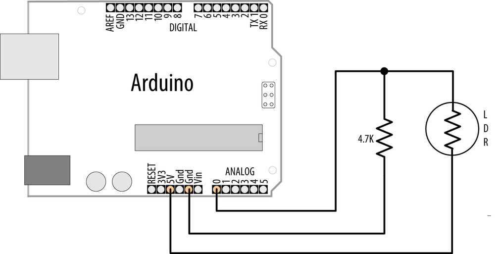
The sketch is based on the LED blinking code from the previous recipe, but instead of using a fixed delay, the rate is determined by a light-sensitive sensor called a light dependent resistor or LDR (see Recipe 6.2). Wire the LDR as shown in Figure 1-8.
Note
If you are not familiar with building a circuit from a schematic, see Appendix B for step-by-step illustrations on how to make this circuit on a breadboard.
The following sketch reads the light level of an LDR connected to analog pin 0. The light level striking the LDR will change the blink rate of the internal LED connected to pin 13:
const int ledPin =  13;     // LED connected to digital pin 13
const int sensorPin = 0;    // connect sensor to analog input 0

void setup()
{
  pinMode(ledPin, OUTPUT);  // enable output on the led pin
}

void loop()
{
  int rate = analogRead(sensorPin);    // read the analog input
  digitalWrite(ledPin, HIGH);   // set the LED on
  delay(rate);                  // wait duration dependent on light level
  digitalWrite(ledPin, LOW);    // set the LED off
  delay(rate);
}
Discussion
The value of the 4.7K resistor is not critical. Anything from 1K
to 10K can be used. The light level on the LDR will change the voltage
level on analog pin 0. The analogRead command (see Chapter 6)
provides a value that ranges from around 200 when the LDR is dark to
800 or so when it is very bright. This value determines the duration
of the LED on and off times, so the blink time increases with light
intensity.
You can scale the blink rate by using the Arduino map function as follows:
const int ledPin =  13;     // LED connected to digital pin 13
const int sensorPin = 0;    // connect sensor to analog input 0

// the next two lines set the min and max delay between blinks
const int minDuration = 100;  // minimum wait between blinks
const int maxDuration = 1000;  // maximum wait between blinks


void setup()
{
  pinMode(ledPin, OUTPUT);  // enable output on the led pin
}

void loop()
{
  int rate = analogRead(sensorPin);    // read the analog input
  // the next line scales the blink rate between the min and max values
  rate = map(rate, 200,800,minDuration, maxDuration); // convert to blink rate
  rate = constrain(rate, minDuration,maxDuration);    // constrain the value

  digitalWrite(ledPin, HIGH);   // set the LED on
  delay(rate);                  // wait duration dependent on light level
  digitalWrite(ledPin, LOW);    // set the LED off
  delay(rate);
}
Recipe 5.7 provides more
details on using the map function
to scale values. Recipe 3.5 has details on
using the constrain function
to ensure values do not exceed a given range.
If you want to view the value of the rate variable on your computer, you can print this to the Arduino Serial Monitor as shown in the revised loop code that follows. The sketch will display the blink rate in the Serial Monitor. You open the Serial Monitor window in the Arduino IDE by clicking on the icon on the right of the top bar (see Chapter 4 for more on using the Serial Monitor):
const int ledPin =  13;     // LED connected to digital pin 13
const int sensorPin = 0;    // connect sensor to analog input 0

// the next two lines set the min and max delay between blinks
const int minDuration = 100;  // minimum wait between blinks
const int maxDuration = 1000;  // maximum wait between blinks


void setup()
{
  pinMode(ledPin, OUTPUT);  // enable output on the led pin
  Serial.begin(9600);       // initialize Serial
}

void loop()
{
  int rate = analogRead(sensorPin);    // read the analog input
  // the next line scales the blink rate between the min and max values
  rate = map(rate, 200,800,minDuration, maxDuration); // convert to blink rate
  rate = constrain(rate, minDuration,maxDuration);    // constrain the value

  Serial.println(rate);         // print rate to serial monitor
  digitalWrite(ledPin, HIGH);   // set the LED on
  delay(rate);                  // wait duration dependent on light level
  digitalWrite(ledPin, LOW);    // set the LED off
  delay(rate);
}
You can use the LDR to control the pitch of a sound by connecting a small speaker to the pin, as shown in Figure 1-9.
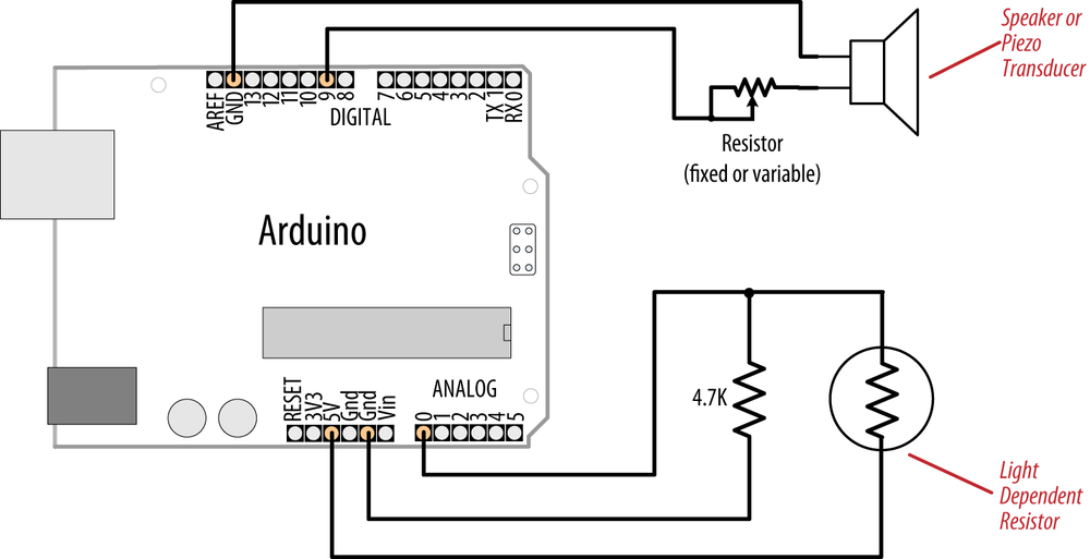
You will need to increase the on/off rate on the pin to a frequency in the audio spectrum. This is achieved, as shown in the following code, by decreasing the min and max durations:
const int outputPin = 9;    // Speaker connected to digital pin 9
const int sensorPin = 0;    // connect sensor to analog input 0

const int minDuration = 1;   // 1ms on, 1ms off (500 Hz)
const int maxDuration = 10;  // 10ms on, 10ms off (50 hz)

void setup()
{
  pinMode(outputPin, OUTPUT);  // enable output on the led pin
}

void loop()
{
  int sensorReading = analogRead(sensorPin);    // read the analog input
  int rate = map(sensorReading, 200,800,minDuration, maxDuration);
  rate = constrain(rate, minDuration,maxDuration);    // constrain the value

  digitalWrite(outputPin, HIGH);   // set the LED on
  delay(rate);                     // wait duration dependent on light level
  digitalWrite(outputPin, LOW);    // set the LED off
  delay(rate);
}
See Also
See Recipe 3.5 for
details on using the constrain
function.
See Recipe 5.7 for a
discussion on the map
function.
If you are interested in creating sounds, see Chapter 9 for a full discussion on audio output with Arduino.
Get Arduino Cookbook, 2nd Edition now with the O’Reilly learning platform.
O’Reilly members experience books, live events, courses curated by job role, and more from O’Reilly and nearly 200 top publishers.

