Schematic Diagrams
When a circuit has more than one or two components, it begins to be difficult to clearly describe it using words alone. A simplified, stylized diagramming technique has been developed over the years to help facilitate this necessary form of communication. An electronic schematic diagram represents individual components as symbols, usually connected with solid lines to indicate the wiring connecting the components. See Figure 4-1.
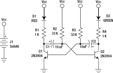
Figure 4-1. An example schematic diagram
Other technical occupations also have their own version of schematics. Any sort of stylized representation that focuses only on the essential components ...
Get Arduino Internals now with the O’Reilly learning platform.
O’Reilly members experience books, live events, courses curated by job role, and more from O’Reilly and nearly 200 top publishers.

