Chapter 4. Specifying Coordinates
IN THIS CHAPTER
Working with absolute, relative, and polar coordinates
Using direct distance entry, orthogonal mode, and polar tracking
Using snap settings
Working with object snaps (OSNAPS)
Locating points
Specifying points in a drawing is one of the most fundamental tasks you do in AutoCAD and AutoCAD LT. Unless you know how to specify a point, you can't draw anything real, whether a house or a gasket. Most objects you draw have a specific size, and you need to specify that information. You draw lines, arcs, and circles by specifying the coordinates of points on the screen. As with most tasks, AutoCAD and AutoCAD LT offer many ways to accomplish this.
Understanding the X,Y Coordinate System
Remember when you studied geometry and trigonometry in high school? You created graphs by drawing X and Y axes. Then you plotted coordinates on graph paper. AutoCAD and AutoCAD LT work the same way.
Look at two displays of the User Coordinate System (UCS) icon, as shown in Figure 4.1. The UCS icon on the left is the default for 2D drawing; the one on the right is the default for 3D drawing and includes the Z axis. In this chapter, I focus on the X and Y axes.
Note
The UCS icon can take on different appearances. See Chapter 8 for details. For information on the UCS icon in 3D work, see Chapter 21.
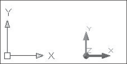
Figure 4.1. The UCS icon shows the direction of the X and Y axes. If you're ...
Get AutoCAD® 2008 and AutoCAD LT® 2008 Bible now with the O’Reilly learning platform.
O’Reilly members experience books, live events, courses curated by job role, and more from O’Reilly and nearly 200 top publishers.

