Discovering New Dimensions
Before digging into the techniques that you use to create dimension styles and the dimensions themselves, here's some AutoCAD dimensioning terminology that you need to understand. If you're already familiar with CAD dimensioning lingo, just skim this section and look at the figures in it. Otherwise, read on.
Anatomy of a dimension
AutoCAD uses the names shown in Figure 14-2 and described in the following list to refer to the parts of each dimension:
- Dimension text: The numeric value that indicates the true distance or angle between points or lines. Dimension text can also include other information in addition to or instead of the number. For example, you can add a suffix, such as TYP., to indicate that a dimension is typical of several similar configurations. AutoCAD's default settings for dimension styles center the dimension text vertically and horizontally on the dimension lines, as shown in Figure 14-2, but you can change those settings to make the text appear in a different location — sitting over an unbroken dimension line, as shown previously in Figure 14-1, for example. See the section “Adjusting style settings,” later in this chapter, for instructions.
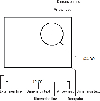
Figure 14-2: The parts of a dimension.
- Dimension lines: In linear dimensions, the dimension lines indicate the true distance between points. Linear dimension lines can be horizontal, vertical, ...
Get AutoCAD® 2012 FOR DUMMIES® now with the O’Reilly learning platform.
O’Reilly members experience books, live events, courses curated by job role, and more from O’Reilly and nearly 200 top publishers.

