Chapter 2. Sensors
2.0 Introduction
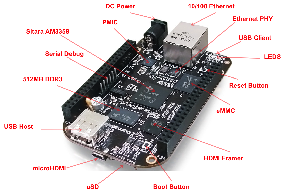
In this chapter, you will learn how to sense the physical world with BeagleBone Black. Various types of electronic sensors, such as cameras and microphones, can be connected to the Bone using one or more interfaces provided by the standard USB 2.0 host port, as shown in Figure 2-1.

Figure 2-1. The USB 2.0 host port
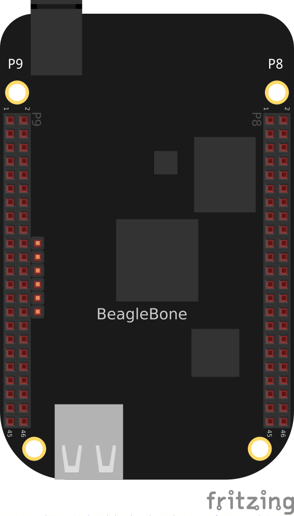
The two 46-pin cape headers (called P8 and P9) along the long edges of the board (Figure 2-2) provide connections for cape add-on boards, digital and analog sensors, and more.

Figure 2-2. The P8 and P9 cape headers
The simplest kind of sensor provides a single digital status, such as off or on, and can be handled by an input mode of one of the Bone’s 65 general-purpose input/output (GPIO) pins. More complex sensors can be connected by using one of the Bone’s seven analog-to-digital converter (ADC) inputs or several I2C buses.
Chapter 3 discusses some of the output mode usages of the GPIO pins.
All these examples assume that you know how to edit a file (Recipe 1.6) and run it, either within the Cloud9 integrated development environment (IDE) or from the command line (Recipe 5.3).
2.1 Choosing a Method to Connect Your Sensor
Problem
You want to acquire and attach a sensor and need to understand your basic options.
Solution
Get BeagleBone Cookbook now with the O’Reilly learning platform.
O’Reilly members experience books, live events, courses curated by job role, and more from O’Reilly and nearly 200 top publishers.

