Chapter 4. Motors
4.0 Introduction
One of the many fun things about embedded computers is that you can move physical things with motors. But there are so many different kinds of motors (servo, stepper, DC), so how do you select the right one?
The type of motor you use depends on the type of motion you want:
- R/C or hobby servo motor
-
Can be quickly positioned at various absolute angles, but some don’t spin. In fact, many can turn only about 180°.
- Stepper motor
-
Spins and can also rotate in precise relative angles, such as turning 45°. Stepper motors come in two types: bipolar (which has four wires) and unipolar (which has five or six wires).
- DC motor
-
Spins either clockwise or counter-clockwise and can have the greatest speed of the three. But a DC motor can’t easily be made to turn to a given angle.
When you know which type of motor to use, interfacing is easy. This chapter shows how to interface with each of these motors.
Note
Motors come in many sizes and types. This chapter presents some of the more popular types and shows how they can interface easily to the Bone. If you need to turn on and off a 120 V motor, consider using something like the PowerSwitch presented in Recipe 3.3.
Note
The Bone has built-in 3.3 V and 5 V supplies, which can supply enough current to drive some small motors. Many motors, however, draw enough current that an external power supply is needed. Therefore, an external 5 V power supply is listed as optional in many of the recipes.
4.1 Controlling a Servo Motor
Solution
We’ll use the pulse width modulation (PWM) hardware of the Bone and control a
servo motor with the analogWrite() function.
To make the recipe, you will need:
-
Servo motor (see “Miscellaneous”)
-
Breadboard and jumper wires (see “Prototyping Equipment”)
-
1 kΩ resistor (optional, see “Resistors”)
-
5 V power supply (optional, see “Miscellaneous”)
The 1 kΩ resistor isn’t required, but it provides some protection to the general-purpose input/output (GPIO) pin in case the servo fails and draws a large current.
Wire up your servo, as shown in Figure 4-1.
Note
There is no standard for how servo motor wires are colored. One of my servos is wired like Figure 4-1: red is 3.3 V, black is ground, and yellow is the control line. I have another servo that has red as 3.3 V and ground is brown, with the control line being orange. Generally, though, the 3.3 V is in the middle. Check the datasheet for your servo before wiring.
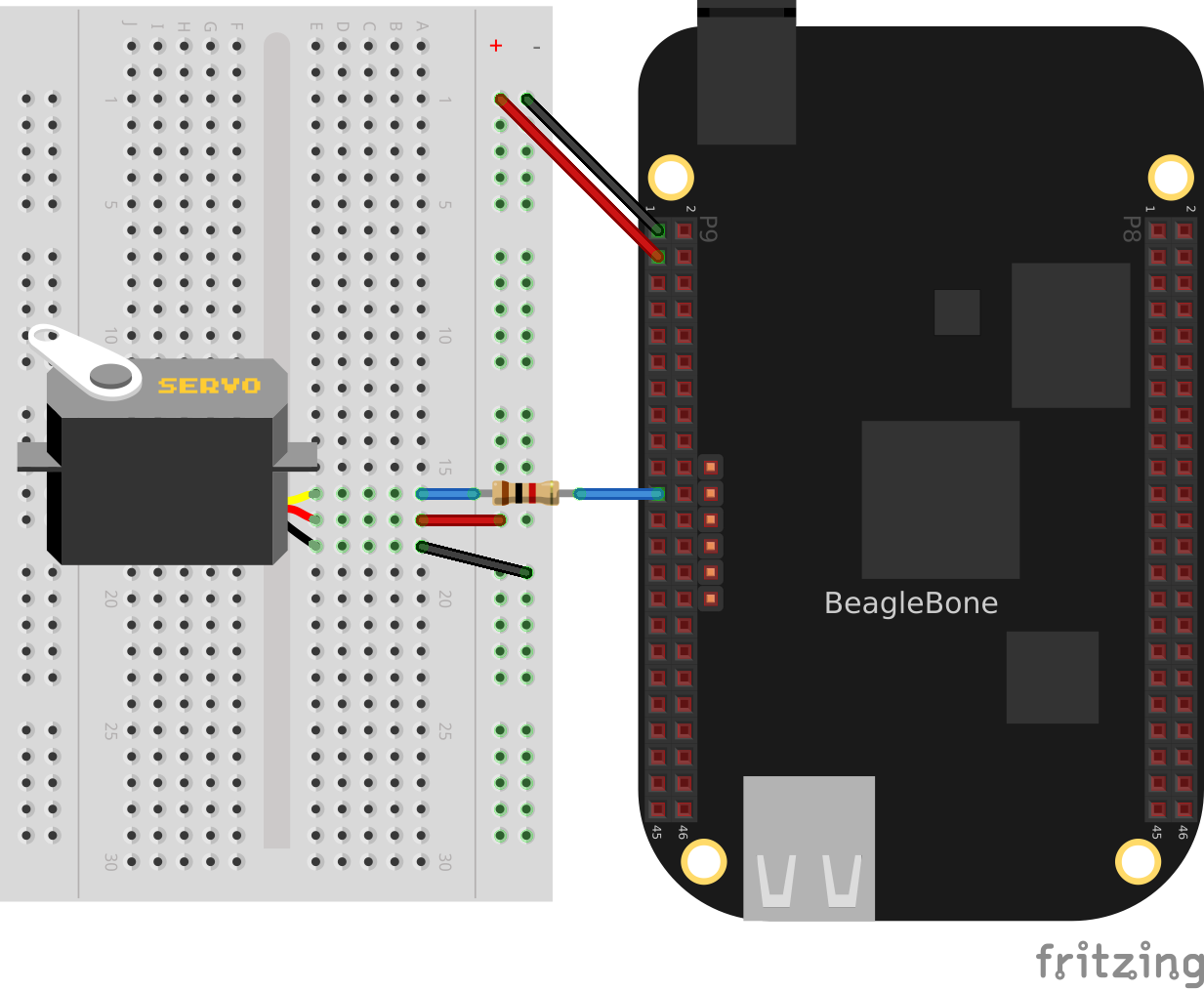
Figure 4-1. Driving a servo motor with the 3.3 V power supply
The code for controlling the servo motor is in servoMotor.js, shown in Example 4-1.
Example 4-1. Code for driving a servo motor (servoMotor.js)
#!/usr/bin/env node

// Drive a simple servo motor back and forth

var b = require('bonescript');

var motor = 'P9_21', // Pin to control servo
    freq = 50,  // Servo frequency (20 ms)
    min  = 0.8, // Smallest angle (in ms)
    max  = 2.5, // Largest angle (in ms)
    ms  = 250,  // How often to change position, in ms
    pos = 1.5,  // Current position, about middle
    step = 0.1; // Step size to next position

console.log('Hit ^C to stop');
b.pinMode(motor, b.ANALOG_OUTPUT, 6, 0, 0, doInterval);

function doInterval(x) {
    if(x.err) {
        console.log('x.err = ' + x.err);
        return;
    }
    timer = setInterval(sweep, ms);
}

move(pos);      // Start in the middle

// Sweep from min to max position and back again
function sweep() {
    pos += step;    // Take a step
    if(pos > max || pos < min) {
        step *= -1;
    }
    move(pos);
}

function move(pos) {
    var dutyCycle = pos/1000*freq;
    b.analogWrite(motor, dutyCycle, freq);
    console.log('pos = ' + pos + ' duty cycle = ' + dutyCycle);
}

process.on('SIGINT', function() {
    console.log('Got SIGINT, turning motor off');
    clearInterval(timer);             // Stop the timer
    b.analogWrite(motor, 0, freq);    // Turn motor off
});
Running the code causes the motor to move back and forth, progressing to successive positions between the two extremes. You will need to press ^C (Ctrl-C) to stop the script.
Discussion
Servo motors are often used in radio-controlled airplanes or cars. They generally don’t spin, but rather turn only 180°, just enough to control an elevator on a wing or steer wheels on a car.
The servo is controlled by a PWM signal, which is controlled by the analogWrite() function, which sends a pulse 50 times each second (50 Hz or every 20 ms). The width of the pulse determines the position of the motor. A short pulse (1 ms, for example) sends the motor angle to zero degrees. A long pulse (2 ms, for example) sets the angle to 180 degrees.
The code in Example 4-1 defines a move() function, which moves the motor to a different angle every time it is called. The setInterval() function schedules sweep() to be called every quarter second (250 ms) to step the servo to a new position.
At the end of the code, the process.on() function detects when the user has pressed ^C (Ctrl-C), stops the timer, and turns off the motor. If you don’t turn off the motor, it will keep buzzing, even if it isn’t moving.
Not all GPIO pins support the PWM hardware; Recipe 3.4 discusses which pins you can use.
Note
If your servo motor needs to run off 5 V, wire it as shown in Figure 4-2. The banded wire attaches the Bone’s 5 V power supply (P9_7) to the power supply on the servo. We are still controlling it with a 3.3 V signal.
Here, we move the banded power wire from the 3.3 V power supply to the Bone’s 5 V power supply on pin P9_7. If the Bone’s built-in 5 V doesn’t supply enough current, or if you need a higher voltage, connect your servo’s power supply wire to an external power supply.
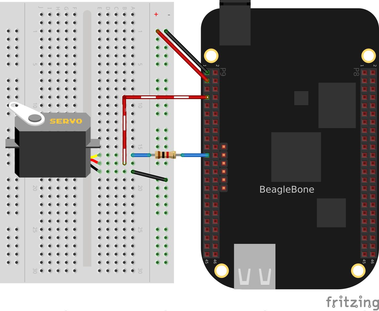
Figure 4-2. Driving a servo motor with the 5 V power supply
Of the motors presented in this chapter, the servo motor is the easiest to drive, because the control line on the servo doesn’t require much current and therefore doesn’t require additional components.
4.2 Controlling the Speed of a DC Motor
Solution
It would be nice if you could just wire the DC motor to BeagleBone Black and have it work, but it won’t. Most motors require more current than the GPIO ports on the Bone can supply. Our solution is to use a transistor to control the current to the bone.
Here’s what you will need:
-
3 V to 5 V DC motor
-
Breadboard and jumper wires (see “Prototyping Equipment”)
-
1 kΩ resistor (see “Resistors”)
-
Transistor 2N3904 (see “Transistors and Diodes”)
-
Diode 1N4001 (see “Transistors and Diodes”)
-
Power supply for the motor (optional)
If you are using a larger motor (more current), you will need to use a larger transistor.
Wire your breadboard as shown in Figure 4-3.
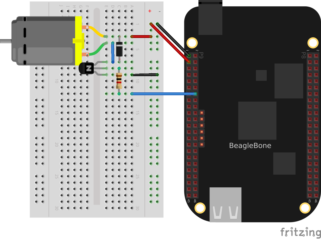
Figure 4-3. Wiring a DC motor to spin one direction
Use the code in Example 4-2 (dcMotor.js) to run the motor.
Example 4-2. Driving a DC motor in one direction (dcMotor.js)
#!/usr/bin/env node

// This is an example of driving a DC motor

var b = require('bonescript');

var motor = 'P9_16',// Pin to drive transistor
    min = 0.05,     // Slowest speed (duty cycle)
    max = 1,        // Fastest (always on)
    ms = 100,       // How often to change speed, in ms
    speed = 0.5,    // Current speed;
    step = 0.05;    // Change in speed

b.pinMode(motor, b.ANALOG_OUTPUT, 6, 0, 0, doInterval);

function doInterval(x) {
    if(x.err) {
        console.log('x.err = ' + x.err);
        return;
    }
    var timer = setInterval(sweep, ms);
}

function sweep() {
    speed += step;
    if(speed > max || speed < min) {
        step *= -1;
    }
    b.analogWrite(motor, speed);
    console.log('speed = ' + speed);
}

process.on('SIGINT', function() {
    console.log('Got SIGINT, turning motor off');
    clearInterval(timer);       // Stop the timer
    b.analogWrite(motor, 0);    // Turn motor off
});
Discussion
This is actually the same code that you used to drive the servo motor (Recipe 4.1). The only difference is how the parameters are set. We are now using the PWM hardware to control the speed of the motor rather than the position. If the duty cycle is 1, the voltage to the motor is on all the time, and it runs at its fastest. If the duty cycle is 0.5, the voltage is on half the time, so the motor runs slower. A duty cycle of 0 stops the motor.
You can use this same setup to drive a solenoid. After all, a solenoid is a DC motor that goes back and forth rather than spinning. Generally, you would drive a solenoid with an on or off signal, as opposed to using a PWM signal.
At the end of the code, the process.on() function detects when the user has pressed ^C (Ctrl-C), stops the timer, and turns off the motor. If you don’t turn off the motor, it will continue to spin.
See Also
How do you change the direction of the motor? See Recipe 4.3.
4.3 Controlling the Speed and Direction of a DC Motor
Solution
Use an H-bridge to switch the terminals on the motor so that it will run both backward and forward. We’ll use the L293D: a common, single-chip H-bridge.
Here’s what you will need:
-
3 V to 5 V motor (see “Miscellaneous”)
-
Breadboard and jumper wires (see “Prototyping Equipment”)
-
L293D H-Bridge IC (see “Integrated Circuits”)
-
Power supply for the motor (optional)
Lay out your breadboard as shown in Figure 4-4. Ensure that the L293D is positioned correctly. There is a notch on one end that should be pointed up.
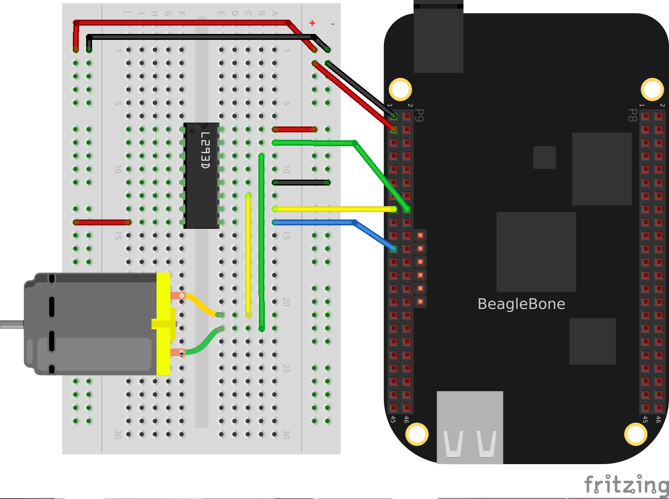
Figure 4-4. Driving a DC motor with an H-bridge
The code in Example 4-3 (h-bridgeMotor.js) looks much like the code for driving the DC motor with a transistor (Example 4-2). The additional code specifies which direction to spin the motor.
Example 4-3. Code for driving a DC motor with an H-bridge (h-bridgeMotor.js)
#!/usr/bin/env node

// This example uses an H-bridge to drive a DC motor in two directions

var b = require('bonescript');

var enable = 'P9_21';    // Pin to use for PWM speed control
    in1    = 'P9_15',
    in2    = 'P9_16',
    step = 0.05,    // Change in speed
    min  = 0.05,    // Min duty cycle
    max  = 1.0,     // Max duty cycle
    ms   = 100,     // Update time, in ms
    speed = min;    // Current speed;

b.pinMode(enable, b.ANALOG_OUTPUT, 6, 0, 0, doInterval);
b.pinMode(in1, b.OUTPUT);
b.pinMode(in2, b.OUTPUT);

function doInterval(x) {
    if(x.err) {
        console.log('x.err = ' + x.err);
        return;
    }
    timer = setInterval(sweep, ms);
}

clockwise();        // Start by going clockwise

function sweep() {
    speed += step;
    if(speed > max || speed < min) {
        step *= -1;
        step>0 ? clockwise() : counterClockwise();
    }
    b.analogWrite(enable, speed);
    console.log('speed = ' + speed);
}

function clockwise() {
    b.digitalWrite(in1, b.HIGH);
    b.digitalWrite(in2, b.LOW);
}

function counterClockwise() {
    b.digitalWrite(in1, b.LOW);
    b.digitalWrite(in2, b.HIGH);
}

process.on('SIGINT', function() {
    console.log('Got SIGINT, turning motor off');
    clearInterval(timer);         // Stop the timer
    b.analogWrite(enable, 0);     // Turn motor off
});
Discussion
The H-bridge provides a simple way to switch the leads on a motor so that it will reverse directions. Figure 4-5 shows how an H-bridge works.

Figure 4-5. H-bridge schematic
The four switches connected to the motor (the big M in the center of Figure 4-5) are the H-bridge. In the left diagram, two switches are closed, connecting the left terminal of the motor to the plus voltage and the right terminal to the ground. This makes the motor rotate in one direction. The diagram on the right shows the other two switches closed, and the plus and grounds are connected to the opposite terminals, making the motor spin the other way.
In the code, in1 and in2 are used to control each pair of switches. (The L293D has four sets of these switches, but we are using only two pairs.) So, to turn clockwise, set in1 HIGH and in2 LOW. To go counter-clockwise, set them the opposite way:
function clockwise() {
    b.digitalWrite(in1, b.HIGH);
    b.digitalWrite(in2, b.LOW);
}

function counterClockwise() {
    b.digitalWrite(in1, b.LOW);
    b.digitalWrite(in2, b.HIGH);
}
The L293D also has an enable pin (pin 9, on the lower right), which is used to control the speed of the motor by using a PWM signal. (See Recipe 4.2 for details on how this works.)
At the end of the code, the process.on() function at the end of the code detects when the user has pressed ^C (Ctrl-C), stops the timer, and turns off the motor. If you don’t turn off the motor, it will continue to spin.
Note
The previous example uses a motor that works with 3.3 V. What if you have a 5 V motor? The banded wire (running from P9_7 to pin 8 of the L293D)
in Figure 4-6 attaches the L293D to the Bone’s 5 V power supply. This will work if your motor doesn’t draw too much current.
If 5 V isn’t enough voltage, or if the Bone can’t supply the current needed, Figure 4-7 shows how to use an external power supply.
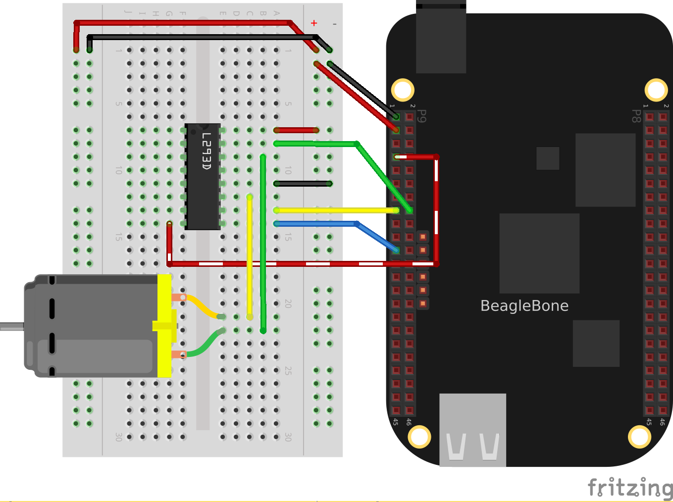
Figure 4-6. Driving a 5 V DC motor with an H-bridge
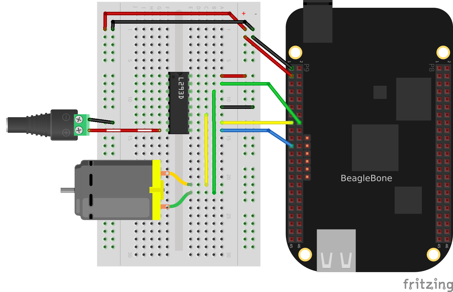
Figure 4-7. Driving a DC motor with an H-bridge and external power supply
The H-bridge provides an easy way to reverse the direction of a DC motor, and attaching the enable to a PWM signal allows you to control the speed.
4.4 Driving a Bipolar Stepper Motor
Solution
Use an L293D H-bridge. The bipolar stepper motor requires us to reverse the coils, so we need to use an H-bridge.
Here’s what you will need:
-
Breadboard and jumper wires (see “Prototyping Equipment”)
-
3 V to 5 V bipolar stepper motor (see “Miscellaneous”)
-
L293D H-Bridge IC (see “Integrated Circuits”)
Wire as shown in Figure 4-8.
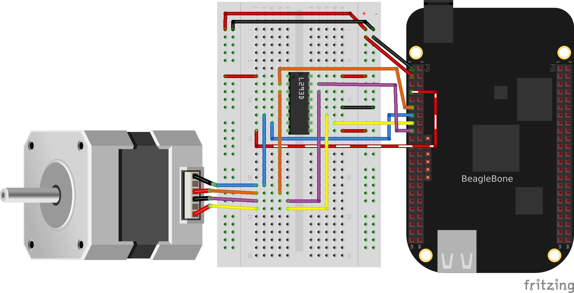
Figure 4-8. Bipolar stepper motor wiring
Use the code in Example 4-4 (bipolarStepperMotor.js) to drive the motor.
Example 4-4. Driving a bipolar stepper motor (bipolarStepperMotor.js)
#!/usr/bin/env node
var b = require('bonescript');

// Motor is attached here
var controller = ["P9_11", "P9_13", "P9_15", "P9_17"];
var states = [[1,0,0,0], [0,1,0,0], [0,0,1,0], [0,0,0,1]];
var statesHiTorque = [[1,1,0,0], [0,1,1,0], [0,0,1,1], [1,0,0,1]];
var statesHalfStep = [[1,0,0,0], [1,1,0,0], [0,1,0,0], [0,1,1,0],
                      [0,0,1,0], [0,0,1,1], [0,0,0,1], [1,0,0,1]];

var curState = 0;   // Current state
var ms = 100,       // Time between steps, in ms
    max = 22,       // Number of steps to turn before turning around
    min = 0;        // Minimum step to turn back around on

var CW  =  1,       // Clockwise
    CCW = -1,
    pos = 0,        // current position and direction
    direction = CW;

// Initialize motor control pins to be OUTPUTs
var i;
for(i=0; i<controller.length; i++) {
    b.pinMode(controller[i], b.OUTPUT);
}

// Put the motor into a known state
updateState(states[0]);
rotate(direction);

var timer = setInterval(move, ms);

// Rotate back and forth once
function move() {
    pos += direction;
    console.log("pos: " + pos);
    // Switch directions if at end.
    if (pos >= max || pos <= min) {
        direction *= -1;
    }
    rotate(direction);
}

// This is the general rotate
function rotate(direction) {
	// console.log("rotate(%d)", direction);
    // Rotate the state acording to the direction of rotation
	curState +=  direction;
	if(curState >= states.length) {
	    curState = 0;
	} else if(curState<0) {
		    curState = states.length-1;
	}
	updateState(states[curState]);
}

// Write the current input state to the controller
function updateState(state) {
    console.log("state: " + state);
	for (i=0; i<controller.length; i++) {
		b.digitalWrite(controller[i], state[i]);
	}
}

process.on('exit', function() {
    updateState([0,0,0,0]);    // Turn motor off
});
When you run the code, the stepper motor will rotate back and forth.
Discussion
Stepper motors are designed to rotate in discrete steps. They operate by turning on one coil (coil 1, for example) in one direction, then turning off coil 1 and turning on coil 2, then turning on 1 in the reverse direction, then 2 in reverse, and then back to 1 forward, as shown in Figure 4-9.
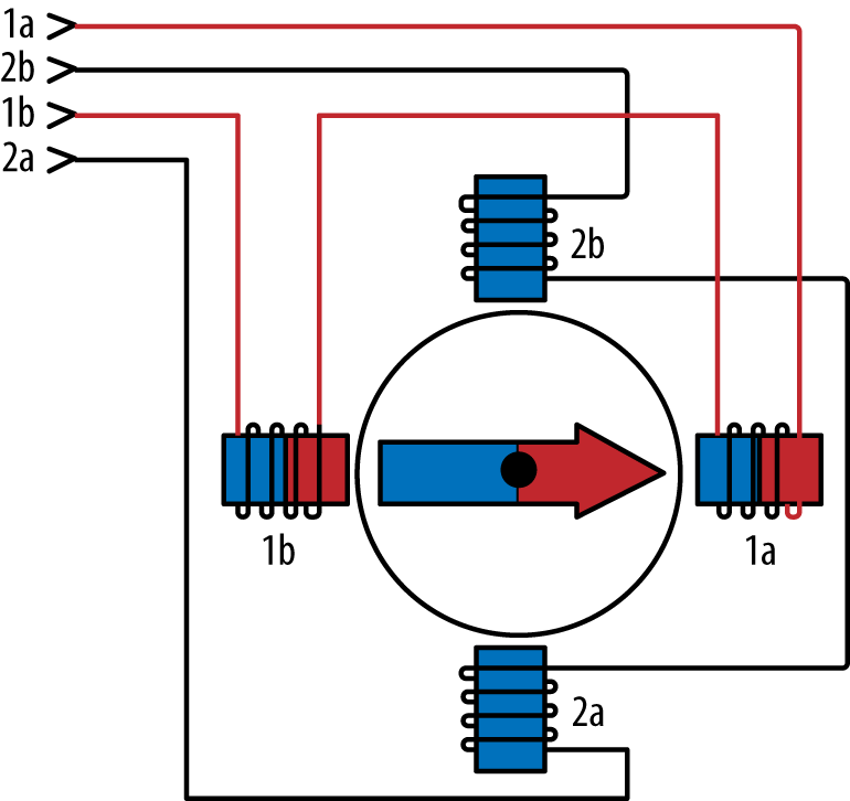
Figure 4-9. Model of a bipolar stepper motor
In Example 4-4 (bipolarStepperMotor.js), the states variable is an array of the four different states listed in the previous paragraph. That is, [1,0,0,0] instructs to turn on coil 1 in the forward direction. After it’s been on for a while, you move to the next state, [0,1,0,0]. This turns off coil 1 and turns on coil 2. Then you go to [0,0,1,0], which turns on coil 1 in reverse, and so on. The H-bridge (see Recipe 4.3) takes care of reversing the coil:
var states = [[1,0,0,0], [0,1,0,0], [0,0,1,0], [0,0,0,1]];
Whenever you step, you just index the next element in the array. If you want to go backward, index the previous element.
There are two other state sequences given in the code, but they aren’t ever used. statesHiTorque is like the original states, except that it has both magnets on at the same time, giving a stronger pull on the motor. The statesHalfStep alternates between having one and two coils on simultaneously to give finer control in the step size:
var statesHiTorque = [[1,1,0,0], [0,1,1,0], [0,0,1,1], [1,0,0,1]];
var statesHalfStep = [[1,0,0,0], [1,1,0,0], [0,1,0,0], [0,1,1,0],
                      [0,0,1,0], [0,0,1,1], [0,0,0,1], [1,0,0,1]];
You can easily try either of these by assigning them to the states variable.
Notice the banded wire running from pin 8 (lower left) of the L293D to P9_7 in Figure 4-8. This is connecting the 5 V power supply on the Bone to the L293D. The Bone outputs 3.3 V on its GPIO pins, but the stepper motor I am using really needs 5 V.
Connecting the 5 V in this way provides 5 V out of the L293D to the stepper motor.
Note
If your stepper motor requires a higher voltage (up to 12 V), you can wire an external power supply, as shown in Figure 4-10.
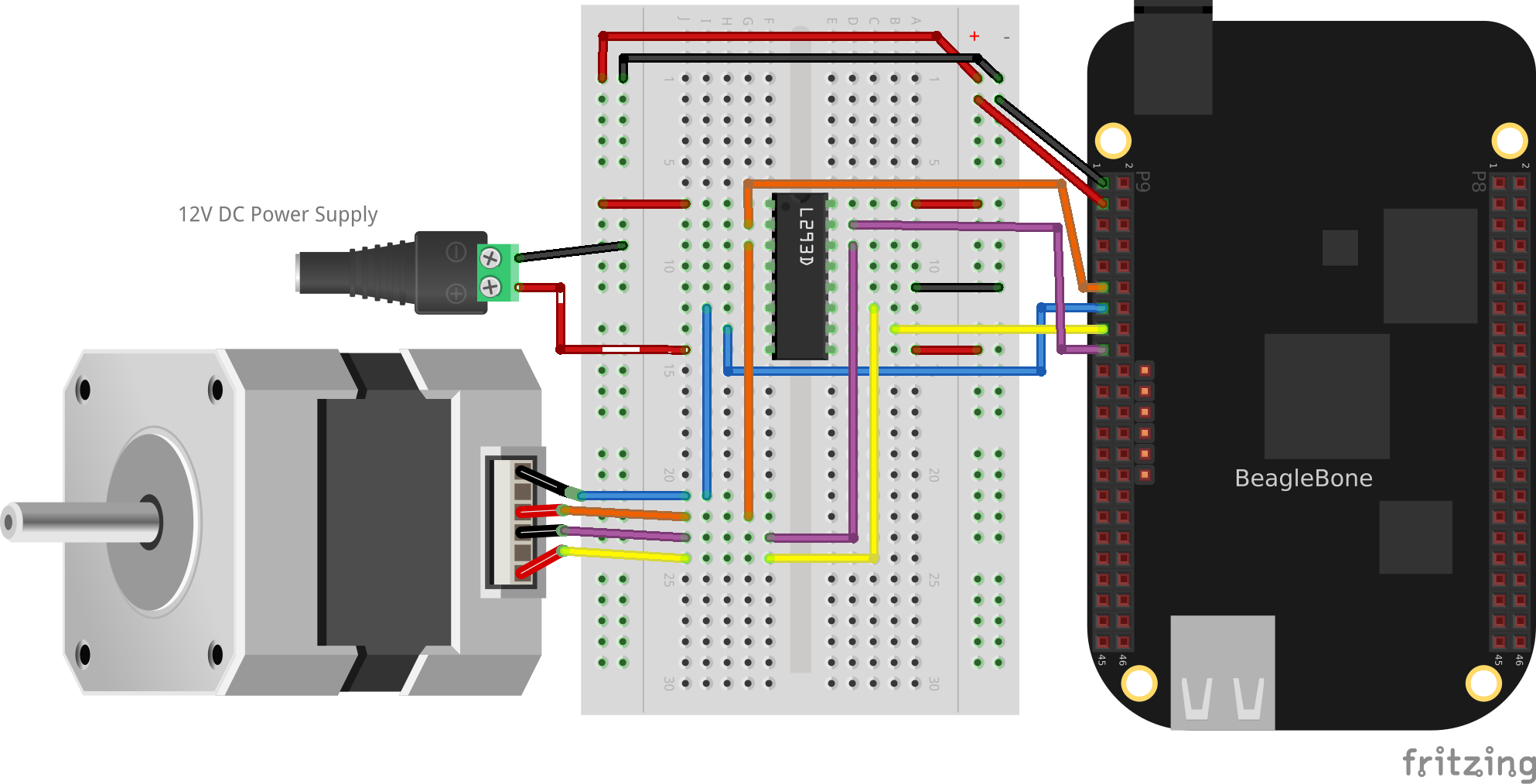
Figure 4-10. Model of a bipolar stepper motor
The stepper motor requires a more complex setup than the servo motor, but it has the advantage of being able to spin, which the servo can’t do.
4.5 Driving a Unipolar Stepper Motor
Solution
If your stepper motor has five or six wires, it’s a unipolar stepper and is wired differently than the bipolar. Here, we’ll use a ULN2003 Darlington Transistor Array IC to drive the motor.
Here’s what you will need:
-
Breadboard and jumper wires (see “Prototyping Equipment”)
-
3 V to 5 V unipolar stepper motor (see “Miscellaneous”)
-
ULN2003 Darlington Transistor Array IC (see “Integrated Circuits”)
Wire, as shown in Figure 4-11.
Note
The IC in Figure 4-11 is illustrated upside down from the way it is usually displayed. That is, the notch for pin 1 is on the bottom. This made drawing the diagram much cleaner.
Also, notice the banded wire running the P9_7 (5 V) to the UL2003A.
The stepper motor I’m using runs better at 5 V, so I’m using the Bone’s 5 V power supply. The signal coming from the GPIO pins is 3.3 V, but the U2003A will step them up to 5 V to drive the motor.
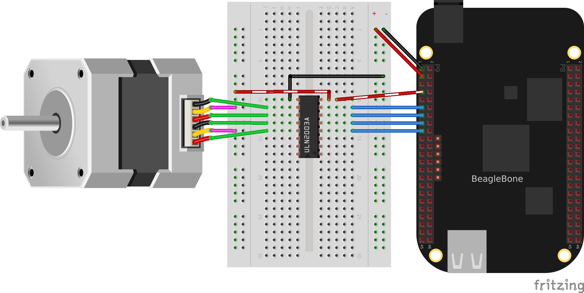
Figure 4-11. Unipolar stepper motor wiring
The code for driving the motor is in unipolarStepperMotor.js; however, it is almost identical to the bipolar stepper code (Example 4-4), so Example 4-5 shows only the lines that you need to change.
Example 4-5. Changes to bipolar code to drive a unipolar stepper motor (unipolarStepperMotor.diff)
var controller = ["P9_11", "P9_13", "P9_15", "P9_17"];
var states = [[1,1,0,0], [0,1,1,0], [0,0,1,1], [1,0,0,1]];
var curState = 0;   // Current state
var ms = 100,       // Time between steps, in ms
    max = 22,       // Number of steps to turn before turning around
The code in this example makes the following changes:
-
controlleris attached to the even-numbered pins on theP9header rather than the odd that the bipolar stepper used. (Doing this allows you to run both types of stepper motors at the same time!) -
The
statesare different. Here, we have two pins high at a time. -
The time between steps (
ms) is shorter, and the number of steps per direction (max) is bigger. The unipolar stepper I’m using has many more steps per rotation, so I need more steps to make it go around.
Discussion
Figure 4-12 shows how the unipolar stepper motor is wired a bit differently than the bipolar.
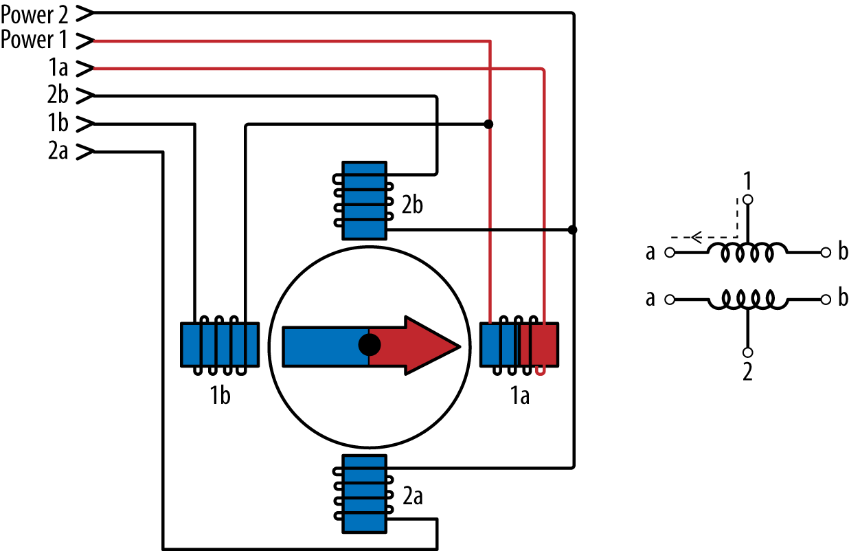
Figure 4-12. Model of a unipolar stepper motor
Each coil is split, so you can access the two sides separately. The difference between the five- and six-wire steppers is that the five-wire steppers have the two power lines connected to each other. The different wiring means a different energizing sequence, as seen in the different states array.
Note
If your stepper requires more voltage, or more current than what the Bone can supply, you can replace the banded wire with an external power supply, similar to the bipolar stepper example (Figure 4-10).
Get BeagleBone Cookbook now with the O’Reilly learning platform.
O’Reilly members experience books, live events, courses curated by job role, and more from O’Reilly and nearly 200 top publishers.

