Chapter 4. Ins and Outs
Congratulations—you now have configurations, communications, and some solid projects under your belt! It’s time to take a closer look at the unique features of the XBee brand of ZigBee radio so we can start building fully scalable sensor networks. We begin with input/output concepts and commands, then immediately put these to use in a small set of progressive projects that whimsically inculcate the basics.
The Story of Data
Before getting into the technical aspects of sensing data, it’s useful to take a step back and consider why it is we want to collect this type of information in the first place. After all, data has no value by itself. In its purest form, data is just a collection of numbers, and one set of numbers is as good as any other. Our real interest in data always comes from the story it might tell us. Gathering data is the first step in noticing new things in the world, proving a hunch, disproving a fallacy, or teaching a truth. It can also be a path to action. Patterns in data can trigger events, shape public policy, or just determine when it’s time to feed the cat. We should always have a purpose in mind when collecting data because that purpose will guide us in how the data is collected. This doesn’t mean we need to know what the data will tell us. Our purpose might be to simply gather results to examine for events or patterns that create new questions. This is known in science circles as exploratory data analysis—a well-accepted form of initial investigation. In other cases, our plan might be to seek out a highly specific event as a trigger for a fixed response. That sounds complicated, but really it describes most doorbells, including the ones you made in the last chapter. Data is collected from a button for the express purpose of triggering an audio alert. Simple enough, but what else could we learn from it?
Direct, Indirect, Subtext
A huge number of electronic sensors are available. Table 4-1 contains a partial list of those within reach of the average tinkerer.
Although the table describes detection of one phenomenon per sensor, each sensor is really capable of simultaneously detecting three distinct but intrinsically related categories of events:
- Direct or proximal phenomena
These are the incidents that directly trigger the sensor apparatus. For example, in the case of a photocell, the proximal event would be photons striking the sensor. Sometimes the proximal phenomenon is not quite as obvious. For instance, a tilt sensor’s proximal trigger would be the repositioning of a metal ball against two electrical contacts. A Hall-effect sensor reports changes in magnetic fields, though that’s only rarely the phenomenon of interest.
- Indirect or distal phenomena
Distal events are the remote causes of the local events actually triggering the sensor. The sun coming out from behind a cloud would be the distal phenomenon that results in a higher reading from a photocell. A window being opened might cause a Hall-effect magnetic sensor to move away from a magnet and open its contacts. These indirect events produce the proximal phenomena that our sensors can respond to, and they are frequently the ones we are most interested in.
- Context and subtext
Sometimes neither the proximal or even distal events are what we’re after. We aren’t interested in magnetic fields at all. In fact, most window openings are not a cause for concern. What we really want to know is if a burglar is entering our house. Our sensor directly detects a change in a magnetic field. That change is an indirect result of a window changing position. But the context is human presence; in this case, definitely a presence that’s undesired. Contextual leaps usually entail some degree of uncertainty. A window might swing open in a gust of wind. A houseguest might open up a window that we’d normally leave closed. This creates a need for determining more information to avoid false alerts or missed alarms. Sensing for multiple phenomena can reduce uncertainty. For example, security systems often include window sensors, motion detectors, and pressure mats. When all of these activate simultaneously, it is a more certain indication of criminal presence than hearing from any one on its own.
When choosing a sensor, always think about which category of events you’re interested in detecting. Sometimes a surprising relationship can exist where a simple sensor can provide reliable indication of an intricate contextual event. A photocell can report when a bathroom cabinet is opened, by detecting that the interior is no longer totally dark. A microphone can detect the wind noise made when someone blows on a pinwheel, and therefore detect both pressure and presence. A switch on the handle of a toilet might indicate human absence if not triggered for two days, signaling an unsecured front door to lock itself.
Now that we’ve thought about sensing in theory, let’s move on to the practical matter of getting the job done.
I/O Concepts
Each XBee radio has the capability to directly gather sensor data and transmit it, without the use of an external microcontroller. This means that you don’t always need something like the Arduino when building simple sensor nodes with XBee radios. In addition, the XBee offers some simple output functions so that basic actuations can also take place without an external microcontroller being present. For example, it’s possible to send digital information directly to a standalone XBee radio to have it turn on a light or start up a motor. For clarity, we’ll refer to these independent input/output functions as XBee direct, to distinguish them from the use of input and output that happens in conjunction with an external microcontroller.
Why XBee Direct?
There are lots of good reasons to use the XBee for direct input or output. By not having an external microcontroller, the overall size of your project is reduced. This is especially important when creating sensors that need to be inconspicuous or fit into tight spaces. By using the XBee alone you’ll also save weight, which can be important if the system is to be lofted skyward in a kite or balloon, or worn on your body, or by your pet. When it comes to wearables, lighter is almost always better. Omitting an external microcontroller also reduces power consumption. This can be a critical advantage for projects that run on batteries, a necessary situation for any project that is truly wireless, and something we’ll talk about more in Chapter 6. Of course, eliminating the external microcontroller means saving money, and for sensor networks with hundreds of nodes, it can mean saving a lot of money. Finally, using the XBee alone is sometimes the least-complicated approach to a project. There’s a lot going for the XBee direct model. However, there are also some important trade-offs to consider.
XBee Direct Limitations
Projects that use the XBee alone for its input/output features may face significant limitations compared to projects that incorporate an external microcontroller such as the Arduino. The XBee has limited input and output pins, with no simple way to extend them. Also, the Series 2 hardware that the ZigBee firmware requires doesn’t currently support analog output at all, which means it can’t be employed to dim a light or control the speed of a motor without additional electronic components. The single biggest limitation is that the basic standalone XBee radio doesn’t allow access to any kind of logic. This means no decisions can be made on the local device and no standalone operations can be performed besides transmitting data or changing the state of digital pins as the result of remote commands.
Note
A new variation of the XBee radio was recently released that incorporates a second microcontroller to allow some forms of local logic. However, this comes at additional cost, will need to be accessed with special programming methods, and requires knowledge of C or Assembly, both lower-level approaches than using Arduino.
XBee I/O Features
The XBee Series 2 hardware offers several flexible features for projects that need simple input and output. There are 10 pins that can be configured either as digital inputs for sensing switches and other things that operate like switches, or as digital outputs for controlling LEDs and small motors directly. Larger loads, including ones that run on alternating current, can be operated using these digital outputs via a relay. The first four of these pins can be configured as analog inputs for sensing a huge array of phenomena that scale over a range, like light, temperature, force, acceleration, humidity, gas levels, and so forth. On the Series 2 radios, there are currently no user-configurable analog or pulse-width modulated (PWM) outputs, so you cannot directly control the speed of a motor or the brightness of an LED light. However, the underlying chipset does support these types of outputs so perhaps they will be available in a future firmware upgrade.
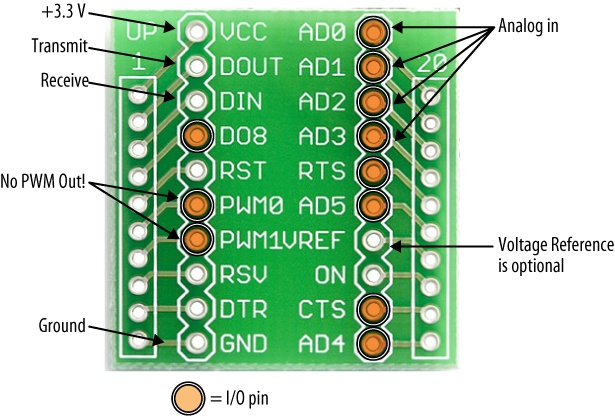
XBees have all these different features available, but this doesn’t mean you can use them all at once! There are only 10 pins total so you if you have all 10 digital inputs configured, you are out of pins and can’t use any digital output or analog input. Happily, the pins can be used in a mix. For example, three analog inputs, four digital inputs, and three digital outputs would be fine. The only other thing to be aware of is that many of the 10 configurable pins are used for other optional duties. These other duties are important in many applications, but they’ve been carefully selected so that they are ones that don’t tend to be needed in remote sensing and actuation projects. For example, some of the duties are serial hardware handshaking (CTS and RTS), an advanced feature that is generally not needed unless there is another microcontroller or logic-based device in the mix. Certain I/O pins do double duty as debugging light outputs for signal strength (RSSI) and association (ASSOC), which are handy for development but generally unimportant on a remote sensor that will not be viewed directly. There are also several pin-controlled sleep features (ON and SLEEP) that are not usually required for standalone sensing or actuation. Of course, on the off chance that one or more of those features is required, it would reduce the number of pins available only by one or two, so you’ll generally have enough left over to cover the vast majority of application projects you can dream up. Table 4-2 shows the input/output pin names with physical numbers, corresponding AT commands, and other functions. Note that DIO8 and DIO9 are not supported in the current firmware so they can’t be used for I/O at this time. Figure 4-1 shows the I/O pins on a breakout board.
Pin name | Physical pin # | AT command | Other functions |
20 | D0 | Analog input, Commissioning Button | |
DIO1, AD1 | 19 | D1 | Analog input |
DIO2, AD2 | 18 | D2 | Analog input |
DIO3, AD3 | 17 | D3 | Analog input |
DIO4 | 11 | D4 | |
DIO5 | 15 | D5 | Association indicator |
DIO6 | 16 | D6 | RTS |
DIO7 | 12 | D7 | CTS |
(DIO8) | 9 | None | Pin sleep control, DTR |
(DIO9) | 13 | None | On/Sleep indicator |
DIO10 | 6 | P0 | Received Signal Strength Indicator (RSSI) |
DIO11 | 7 | P1 | |
DIO12 | 4 | P2 |
AT Configuration I/O Commands
To configure the XBee radio for direct input, output, or both, you’ll use a set of AT commands that select each pin’s mode and the sample rate for sending the data. There are several steps involved in getting this done, so read carefully through this section at least once before starting to configure your radio.
Here’s the basic I/O command set:
ATD0...ATD7Configures pins 0 through 7 for I/O mode (pins 8 and 9 are not supported in the current firmware version). The number after the D indicates which pin you’ll be configuring. The command is followed by a numeric code that indicates whether the pin is tasked with digital input, output, analog input (pins 0 to 3 only), some other function, or nothing at all. For example, to configure I/O pin 2 as a digital input (code 3), the command would be
ATD23. See the I/O settings codes in Table 4-3 for a complete list of the codes.ATP0...ATP2Configures pins 10 11, and 12 for I/O mode (there’s a P3 for pin 13, but it is not supported in the current firmware). Again, the number after the P indicates which pin you’ll be configuring, and is followed by a numeric code to indicate what purpose the pin will serve—digital in, digital out, or nothing. For example, to configure I/O pin 11 as a high digital output (code 5) the command would be
ATP15. Pins 10-12 do not support any analog functions.ATIRThis sets the I/O sample rate—how frequently to report the current pin state and transmit it to the destination address. The rate is set in milliseconds, using hexadecimal notation. So, for example, let’s say you want to take a sample 10 times every second. There are 1,000 milliseconds in a second so we divide this by 10 to get 100 milliseconds. Now we just need to find the hexadecimal equivalent of 100. This happens to be 0x64, so the command would be
ATIR64. To disable periodic sampling, simply setATIRto zero.ATWRDon’t forget to write the configuration to firmware using
ATWRso that the next time your radio powers up it retains the correct settings!
The settings codes for each I/O pin (Table 4-3) designate whether it will do nothing, perform a built-in function, take analog input, take digital input, or give digital output.
ATDx or ATPx followed by: | Purpose: |
0 | Disables I/O on that pin |
1 | Built-in function, if available on that pin |
2 | Analog input, only on pins D0 through D3 |
3 | Digital input |
4 | Digital output, low (0 volts) |
5 | Digital output, high (3.3 volts) |
Note
Analog input pins D0 through D3 read a range from 0 volts to 1.2 volts maximum. Voltages above 1.2 are ignored and result in the same maximum reading. Because most circuits using the XBee Series 2 run at 3.3 volts, if your input is a variable resistor, like a photoresistor, flex sensor, or force sensor, you’ll need to create a voltage divider circuit that cuts maximum voltage by two-thirds to keep it within the range of the analog-digital converter (ADC).
The formula for voltage divider output between the two resistors is:
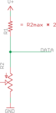
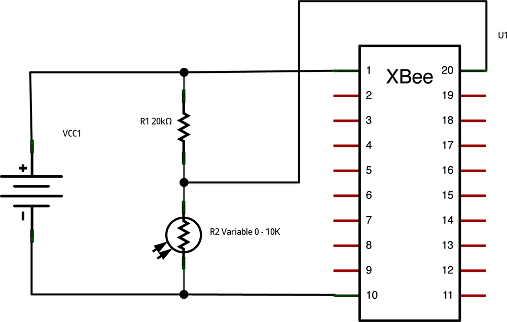
A fast implementation for transforming a 3.3 V input into one that stays below 1.2 V max is to have the fixed resistor R1 be twice the maximum resistance of the variable resistor R2. So in the circuit shown in Figure 4-2, if R2 is a flex sensor with a maximum resistance of 10K ohm, then R1 would be a 20K ohm fixed resistor. Or, for a photocell rated at 300 ohms, a good choice of fixed resistor would be 600 ohms.
Advanced I/O Commands
Several other AT commands may come in handy for projects with special I/O needs. These are worth knowing about even if you don’t need to use them right away. The XBee manual has detailed specifications for each of these commands:
AT%VReturns the current supply voltage for the module. This is useful for keeping track of battery status.
ATPRConfigures the internal 30K ohm pull-up resistors, using a binary value to set for each pin you’ve configured as an input. This is useful if your input component is a momentary digital switch that connects to ground, so you don’t need to add the required external pull-up resistor. By default, the internal pull-ups are all enabled.
ATICConfigures the digital I/O pins to monitor for changes in state, using a binary value to set for each pin. The pin(s) would also need to be configured as digital inputs. When change-detection is enabled, a sample is sent immediately any time a pin shifts from low to high or vice versa. This is useful if you are monitoring a switch, and care about triggering a transmission only when a button is pressed or released.
Romantic Lighting Sensor
Wireless networking is not nearly as tricky as navigating romance. Luckily, the former can help you with the latter, as this next project will demonstrate. Imagine for a moment that you are a brilliant engineer, hacker, interaction designer, or scientist—and perhaps you actually are. Let’s say you’ve mastered math, manual skills, and usability, but nothing in your schooling has prepared you for the daunting task of setting a scene where love can blossom. What to do? The dining table is laid out perfectly; your date is moments away from ringing your wireless doorbell; now how to set the lights? We all know that glaringly bright lighting tends to hamper courtship. This is a date after all, not an interrogation. On the other hand, dimming the lights too far can seem creepy. What you need is a sensing system that lets you know you’ve lit things in the sweet spot for romance.
To get you started, here’s a project that creates a remote wireless lighting sensor with a base station that lights a green LED when the mood is just right. It also happens to be a fine example for developing a variety of your own wireless I/O projects.
Basic Romantic Lighting Sensor
We’ll start by creating a simple wireless lighting sensor that gives feedback at the base station.
Parts
Two solderless breadboards (MS MKKN2, AF 64, DK 438-1045-ND, SFE PRT-09567)
Hookup wire or jumper wire kit (MS MKSEEED3, AF 153, DK 923351-ND, SFE PRT-00124)
One Arduino board (MS MKSP4, SFE DEV-09950, AF 50)
USB A-to-B cable for Arduino (AF 62, DK 88732-9002, SFE CAB-00512)
Two AA battery holders with connection wires (RS 270-408, SFE PRT-09547)
Two AA batteries (alkaline or NIMH rechargeable, fully charged) (RS 23-873, SFE PRT-09100 or PRT-00335)
Two 5 mm LEDs (DK 160-1707-ND, RS 276-041, SFE COM-09590)
One 20K ohm resistor (or twice the max value of your photoresistor) (DK P20KBACT-ND, SFE COM-08374 * 2 in series)
One 10K ohm photoresistor (also called an LDR or light-dependent resistor) (AF 161, DK PDV-P8001-ND, SFE SEN-09088)
One XBee radio (Series 2/ZB firmware) configured as a ZigBee Coordinator API mode (Digi: XB24-Z7WIT-004, DK 602-1098-ND)
One XBee radio (Series 2/ZB firmware) configured as a ZigBee Router AT mode (Digi: XB24-Z7WIT-004, DK 602-1098-ND)
Two XBee breakout boards with male headers and 2 mm female headers installed (AF 126 [add SFE PRT-00116], SFE BOB-08276, PRT-08272, and PRT-00116)
XBee USB Serial adapter (XBee Explorer, Digi Evaluation board, or similar) (AF 247, SFE WRL-08687)
USB cable for XBee adapter (AF 260, SFE CAB-00598)
Wire strippers (AF 147, DK PAL70057-ND, SFE TOL-08696)
Prepare your coordinator radio
Write down your coordinator and router radios’ addresses (printed on the back) so that you can refer to them during configuration:
Coordinator address | Router address |
| |
Follow the instructions under Reading Current Firmware and Configuration in Chapter 2 to configure one of your radios as a ZigBee Coordinator API.
Warning
Your coordinator radio must use the API firmware for this project to work, because I/O data is delivered only in API mode. Be sure to select the API version for your coordinator!
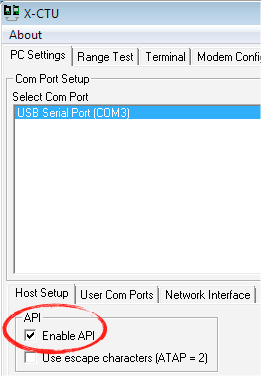
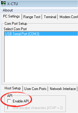
When you change from AT to API mode using X-CTU, you may get an error message that the radio is no longer communicating. Go back to the PC Settings tab and check the Enable API box (Figure 4-3) to enable communications with your radio.
Once a radio has been set to API mode, it can only be configured in X-CTU. You will not be able to make adjustments to this radio’s configuration in CoolTerm or any other terminal program. Use X-CTU to configure the coordinator with a PAN ID (between 0x0 and 0xFFFFFFFFFFFFFFFF) you’ve selected. Write down this PAN ID so you can program your router radio with the same one. Every radio in your network must use the same PAN ID so they can communicate with each other:
Pan ID:
_____________________________
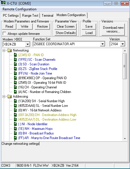
Use X-CTU (Figure 4-4) to set
ATDHto the high part of your router radio’s address (always0013A200for XBees) andATDLto the remainder of your router radio’s address (the unique part of the number you noted above).Click on the Write button to save your settings to the radio.
Prepare your router radio
Follow the instructions under Reading Current Firmware and Configuration in Chapter 2 to configure one of your radios as a ZigBee Router AT.
Warning
Your router radio will use the AT firmware, so you can easily configure it using a serial terminal. Be sure you select the AT version for your router!
When you change from an API radio to an AT radio, you may get an error message that the radio is no longer communicating. If so, go back to the PC Settings tab and uncheck the Enable API Mode box (Figure 4-5).
Label the coordinator radio with a “C” so you know which one it is later on. Label the router radio with an “R.”
Prepare the Sensor Board
We’ll use the CoolTerm terminal program (Mac, Windows) and an XBee Explorer USB adapter again to set up your radios. (If you’re on Linux, see the sidebar A Serial Terminal Program for Linux in Chapter 2.)
Configure your router XBee
Select the router XBee you labeled with an “R” and place it into the XBee Explorer.
Plug the XBee Explorer into your computer.
Run the CoolTerm program and press the Options button to configure it.
Select the appropriate serial port, and check the Local Echo box so you can see your commands as you type them.
Click on the Connect button to connect to the serial port.
Type
+++to go into command mode. You should receive an OK reply from the radio.Select the same PAN ID you entered for your first radio. PAN ID: ______
Type
ATIDfollowed by the PAN ID you selected and press Enter on the keyboard. You should receive OK again as a reply.Enter
ATDHfollowed by the high part of your radio’s destination address—always the same for the XBees. TypeATDH 0013A200and press Enter on the keyboard. You should receive an OK response.Enter
ATDLfollowed by the low part of your radio’s destination address—the eight-character hexadecimal address of the coordinator radio that follows 0013A200. TypeATDLfollowed by that low part of the destination address, then press Enter. You should receive an OK response. Remember that your destination will be the coordinator radio.Enter
ATJV1to ensure that your router attempts to rejoin the coordinator on startup.Enter
ATD02to put pin 0 in analog mode.Enter
ATIR64to set the sample rate to 100 milliseconds (hex 64).Save your new settings as the radio’s default by typing
ATWRand pressing Enter.
Note
It’s not a bad idea to check your configurations after you
enter them. For example, to check that you entered the destination
address correctly, from command mode type ATDL and press Return to see the current
setting.
Connect power from battery to breadboard
Your remote sensor will use a breadboard connected to two AA batteries:
Hook up the positive (usually red) battery lead to one of the power rails on the breadboard.
Hook up the ground (usually black) battery lead to a ground rail on the breadboard.
Hook up power and ground across the breadboard so that the rails on both sides are live.
Router XBee connection to battery
With the router XBee mounted on its breakout board, position the breakout board in the center of your other breadboard so that the two rows of male header pins are inserted on opposite sides of the center trough.
Use red hookup wire to connect pin 1 (VCC) of the XBee to 3-volt battery power.
Use black hookup wire to connect pin 10 (GND) of the XBee to ground.
Photoresistor input
The battery-powered board with the router radio will be your remote sensor. On that board:
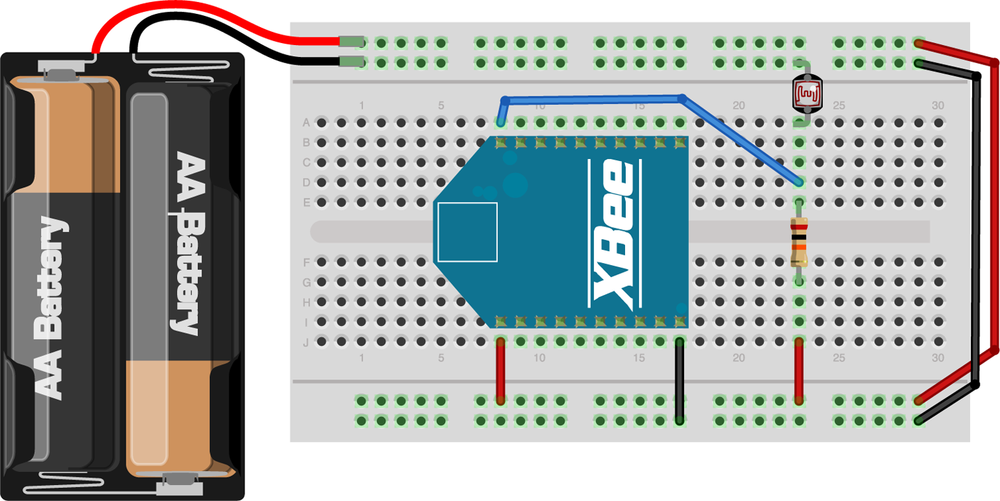
Attach a photoresistor between ground and XBee digital input 0 (physical pin 20).
Make sure you use the 20K ohm (or other value that’s double your photoresistor’s max value) pull-up resistor from digital input 0 to power. This ensures the sensor has a proper voltage divider circuit, which is required to get correct readings.
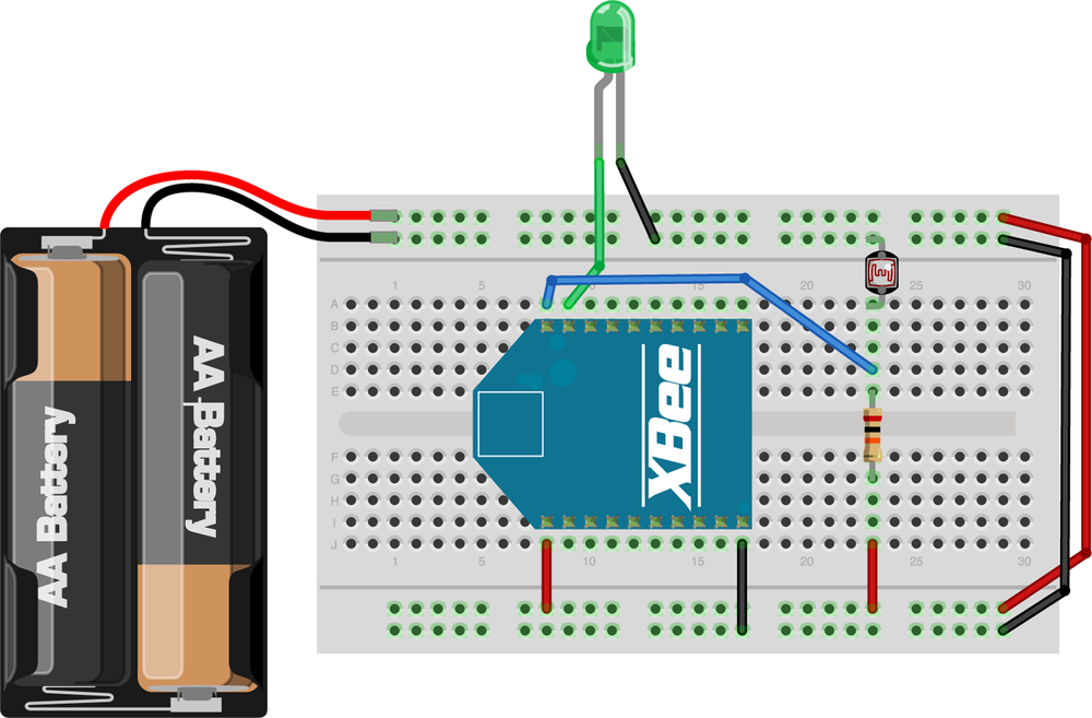
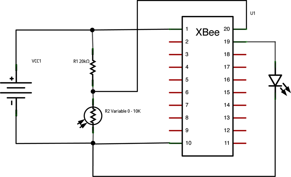
Figure 4-6 shows the layout of the board, and Figure 4-7 shows the schematic.
Prepare the Base Station
Your base station radio will use a breadboard connected to an Arduino board.
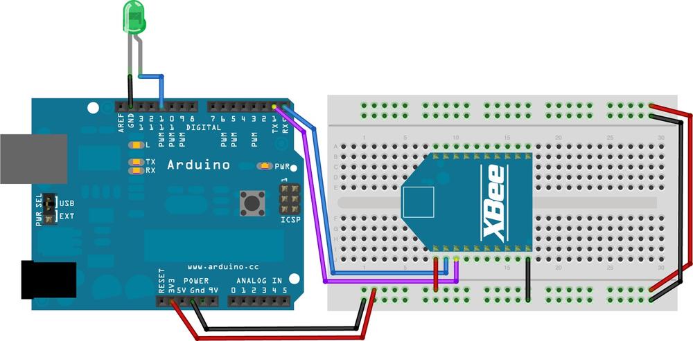
Connect power from Arduino to breadboard
Hook up a red wire from the 3.3 V output of the Arduino to one of the power rails on the breadboard.
Hook up a black wire from either ground (GND) connection on the Arduino to a ground rail on the breadboard.
Hook up power and ground across the breadboard so that the rails on both sides are live.
Warning
Make sure you are using 3.3 V power.
Coordinator XBee connection to Arduino
With the coordinator XBee mounted on its breakout board, position the breakout board in the center of one of your breadboards so that the two rows of male header pins are inserted on opposite sides of the center trough.
Use red hookup wire to connect pin 1 (VCC) of the XBee to 3.3-volt power.
Use black hookup wire to connect pin 10 (GND) of the XBee to ground.
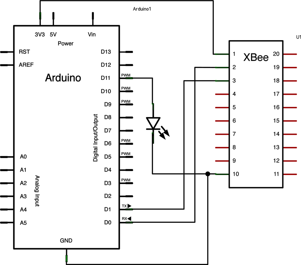
Use yellow (or another color) hookup wire to connect pin 2 (TX/DOUT) of the XBee to digital pin 0 (RX) on your Arduino.
Finally, use blue (or another color) hookup wire to connect pin 3 (RX/DIN) of your XBee to digital pin 1 (TX) on your Arduino.
Light output
Attach the positive (longer) lead of an LED to Arduino digital pin 11.
Attach the shorter ground lead from your LED to ground.
If you prefer to use another output, like an audio buzzer or pager motor, you can hook it up in the same way. Perhaps your romance chops are best demonstrated by a puff of scented air freshener. Then again, maybe a monkey playing the drums is more your style. The key to romance is being yourself, so don’t hesitate to get creative!
Figure 4-8 shows the layout of the board, and Figure 4-9 shows the schematic.
Program the romantic lighting sensor base station
The romantic lighting sensor base station uses the following Arduino program. Upload it to your Arduino board and you’re ready to test the mood:
Warning
When uploading programs to the Arduino board, disconnect the wiring from digital pin 0 (RX) first, then reconnect the wiring after loading.
/*
 * *********ROMANTIC LIGHTING SENSOR ********
 * detects whether your lighting is
 * setting the right mood
 * USES PREVIOUSLY PAIRED XBEE ZB RADIOS
 * by Rob Faludi http://faludi.com
 */

/*
*** CONFIGURATION ***

 SENDER: (REMOTE SENSOR RADIO)
 ATID3456 (PAN ID)
 ATDH -> set to SH of partner radio
 ATDL  -> set to SL of partner radio
 ATJV1 -> rejoin with coordinator on startup
 ATD02  pin 0 in analog in mode
 ATIR64 sample rate 100 millisecs (hex 64)


 * THE LOCAL RADIO _MUST_ BE IN API MODE *

 RECEIVER: (LOCAL RADIO)
 ATID3456 (PAN ID)
 ATDH -> set to SH of partner radio
 ATDL  -> set to SL of partner radio

 */

#define VERSION "1.02"

int LED = 11;
int debugLED = 13;
int analogValue = 0;


void setup() {
  pinMode(LED,OUTPUT);
  pinMode(debugLED,OUTPUT);
  Serial.begin(9600);
}


void loop() {
  // make sure everything we need is in the buffer
  if (Serial.available() >= 21) {
    // look for the start byte
    if (Serial.read() == 0x7E) {
      //blink debug LED to indicate when data is received
      digitalWrite(debugLED, HIGH);
      delay(10);
      digitalWrite(debugLED, LOW);
      // read the variables that we're not using out of the buffer
      for (int i = 0; i<18; i++) {
        byte discard = Serial.read();
      }
      int analogHigh = Serial.read();
      int analogLow = Serial.read();
      analogValue =  analogLow + (analogHigh * 256);
    }
  }

  /*
   * The values in this section will probably
   * need to be adjusted according to your
   * photoresistor, ambient lighting, and tastes.
   * For example, if you find that the darkness
   * threshold is too dim, change the 350 value
   * to a larger number.
   */

  // darkness is too creepy for romance
  if (analogValue > 0 && analogValue <= 350) {
    digitalWrite(LED, LOW);
  }
  // medium light is the perfect mood for romance
  if (analogValue > 350 && analogValue <= 750) {
    digitalWrite(LED, HIGH);
  }
  // bright light kills the romantic mood
  if (analogValue > 750 && analogValue <= 1023) {
    digitalWrite(LED, LOW);
  }

}Troubleshooting
If things don’t work at first, here are some steps to take to try to figure out what’s wrong:
Check all your electrical connections to make sure there are no loose wires and that all the components are connected properly.
Check the coordinator configuration in X-CTU again, including that the correct modem type (XB24-ZB) and function set (ZigBee Coordinator API) have been selected. Also check that the PAN ID, destination high, and destination low are configured as you expect. Remember the destination is the other radio.
Check the router configuration in X-CTU to confirm that the correct modem type (XB24-ZB) and function set (ZigBee Router AT) have been selected. Also check that the PAN ID, destination high, and destination low are configured as you expect, and that ATJV, ATD0, and ATIR have been configured as described above.
Make sure that the Arduino is programmed with the correct code for this project (the basic version above and the feedback version below have different code and must be matched to the correct board setup and radio settings).
The debug LED on the Arduino board (pin 13) will flash if you are receiving data. If this light is flashing but your output light doesn’t change, try adjusting the sensor threshold values in the Arduino code.
An LED placed from the ASSOC pin of the XBee (physical pin 15) to ground should show a flashing light.
An LED placed from the RSSI pin of the XBee (physical pin 6) to ground should show a steady light when the radio is receiving information. If messages stop coming in, this light will time out and go dark after 10 seconds.
Use a multimeter to see if the voltage at the D0 pin of the XBee (physical pin 20) varies with changes in the lighting. It should be somewhere in the range between 0 and 1.2 volts and change as you shadow the light sensor with your hand.
We are not always able to see our own mistakes. Have a friend check everything for you. Sometimes only a second pair of eyes will catch the one (or more) issues standing in the way of success.
When all else fails: Try taking a break and coming back to the project after a good night’s rest. Many of midnight’s intractable puzzles are morning’s simple fix.
Romantic Lighting Sensor with Feedback
The basic sensor works pretty well as long as you are at the base station. However, it’s a pain to run back and forth between the sensor and the base to see if the mood is right. Let’s improve on things by putting the feedback right where the sensor is. This is also a nice example to start with for any project where you want both sensing and actuation on a remote device.
Add light output to the sensor
Attach the positive (longer) lead of an LED to XBee digital input 1 (physical pin 19).
Attach the shorter ground lead from your LED to ground.
Figure 4-10 shows the layout of the board, and Figure 4-11 shows the schematic.
Configure your router XBee
We’ll use the CoolTerm terminal program and an XBee Explorer USB adapter again to set up the radios. The setup is the same as in the basic version above, with the addition of a digital output pin to control the sensor LED:
Select the router XBee you labeled with an “R” and place it into the XBee Explorer.
Plug the XBee Explorer into your computer.
Run the CoolTerm program and press the Options button to configure it.
Select the appropriate serial port, and check the Local Echo box so you can see your commands as you type them.
Click on the Connect button to connect to the serial port.
Type
+++to go into command mode. You should receive an OK reply from the radio.Enter
ATD14to put pin 1 in low digital output mode.Save your new settings as the radio’s default by typing
ATWRand pressing Enter.
Program the romantic lighting sensor with feedback base station
The romantic lighting sensor with feedback base station uses the following Arduino program. Upload it to your Arduino board and you’re ready to test the mood right from the sensor:
Warning
When uploading programs to the Arduino board, disconnect the wiring from digital pin 0 (RX) first, then reconnect the wiring after loading.
/*
 * *********ROMANTIC LIGHTING SENSOR WITH FEEDBACK********
 * detects whether your lighting is
 * setting the right mood and shows
 * you the results on the sensor module
 * USES PREVIOUSLY PAIRED XBEE ZB RADIOS
 * by Rob Faludi http://faludi.com
 */

/*
*** CONFIGURATION ***

 SENDER: (REMOTE SENSOR RADIO)
 ATID3456 (PAN ID)
 ATDH -> set to SH of partner radio
 ATDL  -> set to SL of partner radio
 ATJV1 -> rejoin with coordinator on startup
 ATD02  pin 0 in analog in mode with a photo resistor
        (don't forget the voltage divider circuit--resistor
        to ground is good)
 ATD14  pin 1 in digital output (default low) mode with an
        LED from that pin to ground
 ATIR64 sample rate 100 millisecs (hex 64)


 * THE LOCAL RADIO _MUST_ BE IN API MODE *

 RECEIVER: (LOCAL RADIO)
 ATID3456 (PAN ID)
 ATDH -> set to SH of partner radio
 ATDL  -> set to SL of partner radio

 */

#define VERSION "1.02"

int LED = 11;
int debugLED = 13;
int analogValue = 0;
int remoteIndicator = false;     // keeps track of the desired remote
                                 // on/off state
int lastRemoteIndicator = false; // record of prior remote state
unsigned long lastSent = 0;      // records last time the remote was
                                 // reset to keep it in sync


void setup() {
  pinMode(LED,OUTPUT);
  pinMode(debugLED,OUTPUT);
  Serial.begin(9600);
}


void loop() {
  // make sure everything we need is in the buffer
  if (Serial.available() >= 23) {
    // look for the start byte
    if (Serial.read() == 0x7E) {
      //blink debug LED to indicate when data is received
      digitalWrite(debugLED, HIGH);
      delay(10);
      digitalWrite(debugLED, LOW);
      // read the variables that we're not using out of the buffer
      // (includes two more for the digital pin report)
      for (int i = 0; i<20; i++) {
        byte discard = Serial.read();
      }
      int analogHigh = Serial.read();
      int analogLow = Serial.read();
      analogValue =  analogLow + (analogHigh * 256);
    }
  }

  /*
   * The values in this section will probably
   * need to be adjusted according to your
   * photoresistor, ambient lighting, and tastes.
   * For example, if you find that the darkness
   * threshold is too dim, change the 350 value
   * to a larger number.
   */

  // darkness is too creepy for romance
  if (analogValue > 0 && analogValue <= 350) {
    digitalWrite(LED, LOW);
    remoteIndicator = false;
  }
  // medium light is the perfect mood for romance
  if (analogValue > 350 && analogValue <= 750) {
    digitalWrite(LED, HIGH);
    remoteIndicator = true;
  }
  // bright light kills the romantic mood
  if (analogValue > 750 && analogValue <= 1023) {
    digitalWrite(LED, LOW);
    remoteIndicator = false;
  }

  // set the indicator immediately when there's a state change
  if (remoteIndicator != lastRemoteIndicator) {
    if (remoteIndicator==false) setRemoteState(0x4);
    if (remoteIndicator==true) setRemoteState(0x5);
    lastRemoteIndicator = remoteIndicator;
  }

  // reset the indicator occasionally in case it's out of sync
  if (millis() - lastSent > 10000 ) {
    if (remoteIndicator==false) setRemoteState(0x4);
    if (remoteIndicator==true) setRemoteState(0x5);
    lastSent = millis();
  }


}

void setRemoteState(int value) {  // pass either a 0x4 or 0x5 to turn the pin on/off
  Serial.print(0x7E, BYTE); // start byte
  Serial.print(0x0, BYTE);  // high part of length (always zero)
  Serial.print(0x10, BYTE); // low part of length (the number of bytes
                            // that follow, not including checksum)
  Serial.print(0x17, BYTE); // 0x17 is a remote AT command
  Serial.print(0x0, BYTE);  // frame id set to zero for no reply
  // ID of recipient, or use 0xFFFF for broadcast
  Serial.print(00, BYTE);
  Serial.print(00, BYTE);
  Serial.print(00, BYTE);
  Serial.print(00, BYTE);
  Serial.print(00, BYTE);
  Serial.print(00, BYTE);
  Serial.print(0xFF, BYTE); // 0xFF for broadcast
  Serial.print(0xFF, BYTE); // 0xFF for broadcast
  // 16 bit of recipient or 0xFFFE if unknown
  Serial.print(0xFF, BYTE);
  Serial.print(0xFE, BYTE);
  Serial.print(0x02, BYTE); // 0x02 to apply changes immediately on remote
  // command name in ASCII characters
  Serial.print('D', BYTE);
  Serial.print('1', BYTE);
  // command data in as many bytes as needed
  Serial.print(value, BYTE);
  // checksum is all bytes after length bytes
  long sum = 0x17 + 0xFF + 0xFF + 0xFF + 0xFE + 0x02 + 'D' + '1' + value;
  Serial.print( 0xFF - ( sum & 0xFF) , BYTE ); // calculate the proper checksum
  delay(10); // safety pause to avoid overwhelming the
             // serial port (if this function is not implemented properly)
}
API Ahead
These last code examples contain something we haven’t really looked at yet, API mode. The next chapter will explore the XBee Application Programming Interface, a highly structured way of communicating with your XBee radio. You’ve already used it, so let’s find out how it works and why it is essential to certain projects.
Get Building Wireless Sensor Networks now with the O’Reilly learning platform.
O’Reilly members experience books, live events, courses curated by job role, and more from O’Reilly and nearly 200 top publishers.
