Inductors in AC Circuits
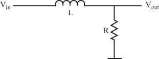
28 Figure 6.40 shows a voltage divider circuit using an inductor, rather than a capacitor.
As with previous problems, consider all the inputs to be pure sine waves. Like the capacitor, the inductor cannot change the frequency of a sine wave, but it can reduce the amplitude of the output voltage.
The simple circuit, as shown in Figure 6.40, opposes current flow.
In many cases, the DC resistance of the inductor is low, so assume that it is 0 ohms. For the next two problems, make that assumption in performing your calculations.
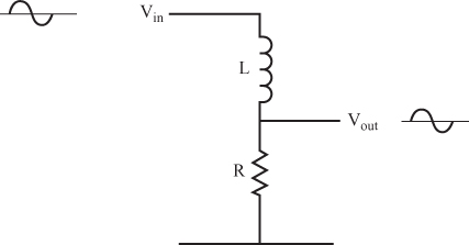
29 You can calculate the voltage output for the circuit shown in Figure 6.41 with the voltage divider formula.
Question
What is the formula for Vout? _____
30 Find the output voltage for the circuit shown in Figure 6.42.
Get Complete Electronics Self-Teaching Guide with Projects now with the O’Reilly learning platform.
O’Reilly members experience books, live events, courses curated by job role, and more from O’Reilly and nearly 200 top publishers.


