November 2002
Intermediate to advanced
320 pages
9h 45m
English
Combining resistors and capacitors can
yield some interesting and useful effects. A resistor-capacitor
combination is known as an RC circuit, and they
can take one of three forms. In the first form, the resistor and
capacitor are in parallel (Figure 2-14).
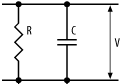
Figure 2-14. Resistor and capacitor in parallel
Now, what does this do? A voltage (V) applied across the pair will charge the capacitor (as well as some current flowing down through the resistor). When the applied voltage is removed, the capacitor will discharge through the resistor. The resistor will limit the rate of discharge, since it limits current flow. From Ohm’s Law, we have that:
I = -V / R
(The negative voltage is because we’re discharging the capacitor.) Now, the current flow out of a capacitor is given by:
I = C * dV/dt
So, we have:
dV/dt = -V / RC
Integrating this with respect to time, with zero initial conditions, gives us:
V = e-t/RC
This gives us the discharge waveform shown in Figure 2-15, which represents the voltage across the capacitor.
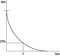
Figure 2-15. Discharge of a parallel RC circuit
A parallel RC circuit will provide an exponential decay in the output
voltage. The value for t when the output voltage is at 37% of the
maximum is known as the time constant for the circuit and is simply the product of R and ...
Read now
Unlock full access


