May 2005
Beginner to intermediate
398 pages
12h 12m
English
You won't get very far in electronics unless you know how to draw and read schematics. They crop up everywhere, and understanding them is a must. The schematics are like an architect's blueprint. They show what components will be used in a circuit and how they are connected together. The schematics may also include other information such as construction directives. A schematic may have a list of revisions indicating what changes have been made to the original design. These are commonly called Engineering Change Orders (ECOs). As a design grows and changes over time, it's a good idea to keep track of what changes were made and, more importantly, why they were made. Just as commenting source code is important, so is keeping track of the ECOs.
You will come across two types of schematics. There are the schematics you see in datasheets, books (like this one), and other technical documents. These schematics will just show the circuit (or partial circuit) and maybe a note or two, and that's all. The other sort of schematic is the actual drawing(s) used to generate a Printed Circuit Board (PCB). These schematics represent a full system design and will often have a title block located in the lower right of the sheet, indicating what the sheet represents, who drew it, and when. Figure 4-5 shows a sample title block.
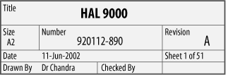
Figure 4-5. Title block
Essentially, there are two ...
Read now
Unlock full access


