Even a conductor (such as a metal wire) is not 100% efficient at conducting current flow. As current flows through the wire, energy will be lost as heat (and sometimes light). For very small currents, this energy loss is negligible, but for large currents, the loss can cause the conductor to become quite hot (an effect utilized in toasters) or glow brightly (light bulbs). This loss of energy results in a voltage difference across the wire (or component). The component is said to resist the current flow. This resistance (also known as impedance , although impedance is somewhat more complex than simple resistance) is measured in Ohms (unit symbol "Ω," equation symbol "R"). In schematics, it is common to leave off the Ω symbol, so 100 kΩ is usually written as just 100 k.
Tip
On a schematic, a 4.7 kΩ value is often not written as 4.7 k, but rather as 4k7. The reason is that it is too easy for a decimal point to be missed, or lost when the document is photocopied. The solution is to place the multiplier ("k") in the position of the decimal point. Resistors such as 24.9 Ω are written as 24R9.
This convention is used by design engineers in most of the world. However, in North America it is only sometimes followed.
The relationship between voltage, current, and resistance is known as Ohm's Law , and is given by:
V = I * R
For a fixed resistance, a varying voltage will produce a varying current, while a constant voltage will produce a constant current. Hence, a varying voltage source is known as an Alternating Current source (or AC), while a constant voltage source is known as a Direct Current source (DC). An AC voltage is normally specified as VAC, while a DC voltage is either VDC or more often just V.
Tip
The stuff that comes out of your wall socket is AC, and is nominally 110-120 VAC (at 60 Hz) if you live in North America; 100 VAC if you're in Japan (50 Hz in the eastern half [Tokyo] and 60 Hz in the western half [Osaka, Kyoto, and Nagoya]); and 220-240 VAC (at 50 Hz) if you're in Australia, New Zealand, the UK, or Europe. All digital electronics, and that includes computers, use DC internally and operate at typical voltages of either 5 V or 3.3 V. (Some digital electronics will operate at voltages as low as 1.8 V or lower.) The power supply of the computer (or TV or stereo or...) converts the high-voltage AC supply into the lower DC required by the electronics. The AC adaptor or plug pack (charger) for your cell phone is also an example of a power supply.
For a given voltage difference, the smaller the resistance, the larger the current flow. Conversely, the bigger the resistance, the smaller the current flow. In this way, resistance can be used to limit the current flow through a particular part of a circuit. Special components, known as resistors, are produced for precisely this purpose. Resistors are part of a family of devices known as passive components .
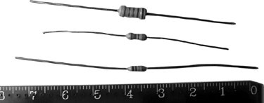
Figure 4-14 shows "through-hole" resistors. From top to bottom, they are 0.5 W, 0.25 W, and 0.125 W, respectively.
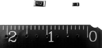
Figure 4-15 shows surface-mount resistors. Surface-mount technology is now far more common than the older "through-hole" style of component. The components shown in Figure 4-15 are a "1206" footprint (left) and a "0603" footprint (right).
There are smaller footprints than these available, but if you're hand-soldering, you are more likely to suffer a nervous breakdown before you successfully solder the component to the circuit board!
The schematic component symbols for a resistor are shown in Figure 4-16. Both symbols mean the same thing. The more commonly seen symbol is on the left.
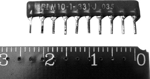
A resistor may be used to pull up (or pull down) a signal line to a given voltage level. If you have many pull-up resistors in your circuit, all of the same value, it may be convenient to use a resistor network, or "resnet," shown in Figure 4-17. Resnets combine several resistors (typically eight, but available in other sizes as well) in a single package. All the resistors are tied to one pin, which is connected to the power supply such that all resistors act as pull-ups.
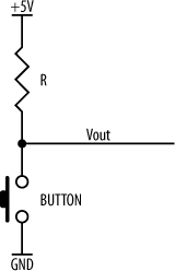
Figure 4-18 shows a pull-up resistor and a push button. When the button is open (not pressed), there is no current flow through the resistor, and, therefore, the voltage at VOUT is (in this case) +5 V. (Since there is no current flow through the resistor, there is no voltage drop across it.) When the button is pushed, VOUT is connected to ground, and, consequently, current will flow through the resistor. This simple circuit can be used to switch an input between two logic level thresholds.
Resistors may be daisy-chained together to increase resistance. This is known as a series connection (Figure 4-19).
The combined total resistance is given by the relation:
RTOTAL = R1 + R2
The current flow through any of the components in series connection will be the same for each component. In other words, the current flowing through the first resistor will be the same as that flowing through the second resistor. This derives from Kirchhoff's Current Law .
Tip
The current flowing through a given circuit point is equal to the sum of the currents flowing into that circuit point, and is also equal to the sum of currents flowing out of that circuit point.
In other words, what flows in must flow out.
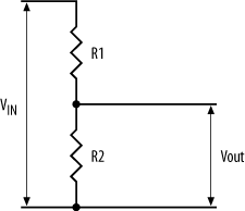
Series resistors may be used to create a voltage divider (Figure 4-20) to provide an intermediate voltage.
The output voltage is given by:
VOUT = VIN * R2 / (R1 + R2)
For example, if the input voltage is 5 V, and the two resistors are both 1 kΩ, then the output voltage is:
   VOUT    = 5V * 1k / (1k + 1k)
      = 5V * 1k / 2k
      = 5V * 0.5
      = 2.5V
As you would expect, a voltage divider using equal resistors halves the input voltage.
Resistors combined in parallel (Figure 4-21) will decrease the total resistance.
The combined total resistance is given by the relation:
RTOTAL = 1 / (1/R1 + 1/R2)
The voltage drop across R1 must be the same as the voltage drop across R2. However, unless R1 is equal to R2 (and there is no requirement for them to be so), the current flow through each will be different. This is derived from Kirchhoff's Voltage Law .
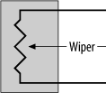
A potentiometer (also known simply as a "pot," "trimmer," or "trim pot") is just a variable resistor. The schematic symbol for a pot is shown in Figure 4-22. Pots are normally mechanical components and are manually adjusted. Your stereo probably uses pots for its volume, bass, and treble controls. The brightness and contrast knobs for monitors and LCDs are also potentiometers.
A standard potentiometer consists of two terminals (the upper and lower pins in the diagram) that connect to either end of a resistor. A third terminal, known as the wiper , moves up or down the resistor, effectively tapping into the voltage present at a given point. Move the wiper one way, and the amount of resistance the wiper sees is increased. Move it the other way, and the resistance decreases.
There are many different types of pots available. Figure 4-23 shows several pots, including a slider pot and two types of rotary pot. Usually, the pot is fitted inside the equipment casing with the wiper shaft poking through an appropriate hole or slot. A knob is then screwed to the shaft.
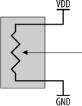
Mechanical pots come in a variety of resistance ranges, and their accuracy is not particularly good. They may be used to provide an adjustable voltage output (Figure 4-24) or simply to vary the resistance used in an analog circuit.
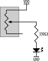
As a simple example, you could use a pot to vary the intensity of a LED by varying the current flow through it. A circuit to do this is shown in Figure 4-25. Here, the fixed resistance between the LED's anode and the pot's wiper is 330Ω. By adjusting the wiper, we add to this resistance, thus decreasing the current flow through the LED and reducing its brightness.
Note how one terminal of the pot is unconnected. This is fine, since in this case we are not using the pot to provide an intermediate voltage between two values. Rather, we are simply using the pot as a variable resistor, increasing the impedance between the wiper and VDD.
Get Designing Embedded Hardware, 2nd Edition now with the O’Reilly learning platform.
O’Reilly members experience books, live events, courses curated by job role, and more from O’Reilly and nearly 200 top publishers.
