This chapter focuses on the selection of appropriate LAN technologies for a network. Many options are available. At the more traditional end of the LAN technology spectrum, we have various flavors of Ethernet and Token Ring. Competing with these technologies are some very interesting modern alternatives such as ATM and wireless networking. Each of these different technologies has its strengths and weaknesses. Some are strikingly effective in certain situations, while awkward and difficult in others.
You should consider four main factors when selecting a LAN technology:
Cost efficiency
Installed base
Maintainability
Performance
One of my central assumptions throughout this book is that the network is built for some business reason. It may not directly involve making money, but there must be some benefit to having the network that justifies the expense of building it. Clearly, the benefit is never infinite, so as network designers, we have a responsibility to build a network that meets the requirements for the lowest possible cost.
This problem is particularly important in the selection of network technologies. The classic example is that Token Ring cards for PCs are more expensive than the equivalent Ethernet cards. This fact alone has explained why so many organizations have undergone expensive changes in their LAN infrastructure to use more cost-effective options. As discussed previously, Token Ring has many performance benefits over Ethernet. But if the cost of Ethernet is low enough and the cost of Token Ring is high enough, then you can engineer around the performance benefits to build an Ethernet network that is at least as good as Token Ring, but less expensive. Or, you may decide to spend more money on Token Ring and get better performance.
Similarly, you could get a high-performance network by running Gigabit Ethernet to every desk. But the cost of doing this would be orders of magnitude higher than the same network using Fast Ethernet. There may still be valid business reasons for wanting to build the faster network. However, it is more likely that a hybrid of the two approaches would meet all of the business requirements with a much more attractive budget.
In general, faster technology is more expensive. This is not universally true, however. Fast Ethernet equipment has become nearly ubiquitous, making the cost of building a Fast Ethernet network similar to the cost of building a regular 10Mbps Ethernet. This is even truer of the 4Mbps and 16Mbps Token Ring—it is now difficult to find Token Ring equipment that doesn't support both standards.
The other important cost/performance decision in both Ethernet- and Token Ring-based networks is the granularity of shared and switched segments. The finest granularity network has a switch port for every end device, which has significant performance benefits—particularly because it allows full-duplex operation. However, switch ports are generally more expensive than hub ports. A more cost-effective solution might involve a hybrid network in which some important end devices are directly attached to switch ports, while others are grouped in small numbers on hubs.
Another important economy involves the use of unmanageable Access devices. Small workgroup hubs and switches with no management capabilities are available for remarkably low prices. In the same vein, it is still possible to build an old-fashioned 10Base2 network, using a long piece of coax cable (often called "thin-net"), for almost nothing.
These inexpensive Access options definitely have their place. They may be ideal for the home or small office LAN. They can also be used to increase the effective port density of the network's Access Level by allowing small groups of users to share ports, as shown in Figure 4-1. This figure shows a Distribution Area containing two Distribution switches and three Access switches. Workgroup hubs and workgroup switches are connectd to these Access switches. Some users are connected through the workgroup devices and some are connected directly to the Access switches. Note that I have shown some of these workgroup devices with dual attachments to the Access switches to provide extra redundancy.
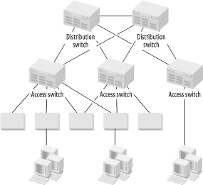
This approach works well, but two main structural disadvantages should be considered. First, even if the end devices are able to connect to a workgroup switch at full-duplex Fast Ethernet speeds, they are still constrained by the uplink speed to the Access switch. If the Access switch is also Fast Ethernet, then remember that these end devices must share that link. This option may or may not be acceptable, given the application traffic patterns.
The second disadvantage is the increased probability of failure. The diagram shows that some of the workgroup devices have dual connections to the Access switches, and having these connections is a good way of helping to reduce the net probability of failure. However, workgroup devices are generally not built for the same level of serious use as the chassis switches that I prefer for the Access switches. Specifically, they often have external power supplies of similar quality to those used for low-end consumer electronics.
Augmenting the network's Access Level with workgroup hubs or switches (or passive MAUs in Token Ring networks) is sometimes a reasonable way to reduce costs. Giving up manageability can be dangerous, though, or at least inconvenient. Connecting end devices directly to Access switches allows control over their VLAN membership. Connecting these devices through an intermediate workgroup hub or switch, however, generally means that every device on the workgroup hub or switch must be part of the same VLAN. This requirement affects flexibility.
A more serious problem is the loss of fault management information. An unmanageable workgroup hub or switch cannot tell you when one of the devices misbehaves or when a cable is faulty. It can't tell you when its power supply is overheating. You might be able to get some information about an ill-behaved device somewhere on a workgroup hub by looking at the more complete management information on the Access switch. It can be difficult to narrow down which device is in trouble, though.
Most seriously, if there are problems with one or more devices connected to a workgroup switch, then the only noticeable result will be performance problems for the other devices in that workgroup. The workgroup switch will not pass bad frames to the Access switch,[1] and it can't complain about the bad frames it receives from its end devices. It is possible to have a serious problem that simply will never be seen unless the users are diligent about complaining.
Installed base is another facet of cost effectiveness. The chances are slim that you are building a new network from scratch. In most cases, there is existing equipment, existing applications, servers, and a cable plant. A significantly cheaper alternative network technology may be available. If migrating to that means that you have to absorb a high cost in changing your installed base, then simply staying with the existing technology may be more cost-effective.
For example, a large company may make extensive use of native Token Ring protocols to connect to legacy mainframe equipment. Token Ring equipment is more expensive than Ethernet equipment, but after factoring in the cost of replacing the mainframe, rewriting the applications to use TCP/IP, and changing every end device to use this new application, they probably won't want to make the change.
This is where it is useful to have a long-term strategic information technology vision for the entire organization. If you have a long-term goal to phase out these legacy applications, then you need to build a network that can accommodate a phased-in migration to the target technology. Perhaps you will migrate the Core of the network from Token Ring to Fast and Gigabit Ethernet with TCP/IP routing and use DLSw to tunnel the native Token Ring protocols. Then, when the new servers and applications are available, you can migrate user devices in relatively small groups.
An installed base doesn't need to cripple a network, but it can limit your design options temporarily.
One of the biggest potential hidden costs in a network is maintenance. I have mentioned how using unmanageable workgroup devices in the Access Level of the network can make it harder to find problems. I previously mentioned that the design principle of simplicity makes network maintenance easier. Remember that these are not just annoyance factors for the engineer who gets stuck with the ultimate responsibility for running the network. There are costs are associated with these issues.
The trouble is that quantifying these costs can be extremely difficult. How can you tell, for example, that cutting a particular corner will result in needing an extra staff member to keep the network going? Only experience can tell you what the hidden costs are. In general, since your design goals are centered on reliability, the more corners you cut, the less reliable the results will be. Lower reliability generally translates into higher maintenance costs.
And this topic brings us to performance considerations. You always want to build the fastest and best network you can for the money. Of course, by "best," I mean that the network best fulfills the business application requirements. A brilliant network with unbelievable throughput and low latency is useless if it doesn't support the applications for which it was built.
I mention performance last because it is far too easy to get absorbed in abstract issues of technology improvement. You always have to bear in mind that a network is built for a business reason. It has a budget that is based on how much money this business goal is worth to the organization. If you spend more on building and maintaining the network than it is worth to the organization, either through money saved or revenue earned, then the network actually hurts the organization more than it helps.
Within these limitations, your goal is to build the best network that you can. That also implies that you have to select technology that is appropriate to what you want to accomplish. Part of a LAN may serve an environment where cabling is impossible, so wireless technology could be a natural fit. But wireless technology tends to offer relatively poor bandwidth and latency compared to a similar network built with Fast Ethernet. When selecting appropriate technology, you have to be sensitive to these trade-offs and understand the strengths and weaknesses of the different options available to you.
Ethernet is a bus topology LAN technology with a collision-based mechanism for dealing with contention. Physically, there are several different options for implementing an Ethernet network. I am generally including Fast Ethernet in these comments because the similarities between Ethernet and Fast Ethernet are strong. I will explicitly note where the comments do not apply to both.
Physical implementations of Ethernet and Fast Ethernet are generally determined by their IEEE designations. For 10Mbps standard Ethernet, the most common option today is 10BaseT. This option uses standard twisted pair cabling, such as Category 5 (although 10BaseT also works well over Category 3 cable plants). Other options include 10Base2 and 10Base5, which implement the LAN bus with an extended cable.
In 10Base2 (also called "thin-net"), the cable is an inexpensive 50Ω impedance coaxial cable that is terminated at both ends with an impedance-matching resistor. Devices connect to the wire by means of T-junction connectors along the length of the cable. Some end devices are equipped with 10Base2 connectors, but a transceiver is frequently required. I will discuss transceivers later in this section.
10Base5 (also called "thick-net") is less common these days because it is difficult to maintain and considerably more expensive than higher speed options. This system uses a thick coaxial cable with considerably longer distance limitations than 10Base2 (500 meters for 10Base5 versus 185 meters for 10Base2). Devices connect to the wire using a "vampire tap," which uses a retractable spike to connect to the wire in the middle of the cable. A transceiver is then required to connect this tap connector to the end device.
It is safe to consider both 10Base2 and 10Base5 as essentially obsolete technology, but they are still in use in some older networks, which is why I mention them here.
Besides copper-based Ethernet technologies, several different fiber optic systems are grouped together under the general IEEE title of 10BaseF. The most common 10Mbps fiber optic Ethernet standard is 10BaseFL. Other options exist, such as 10BaseFB and 10BaseFP. The term FOIRL (Fiber Optic Inter-Repeater Link) is often used generically to describe any 10BaseF transceiver, although technically, FOIRL describes an earlier standard.
Since the same fiber optic cabling is capable of transmitting Gigabit Ethernet, there is seldom much point in installing new 10BaseF systems. It is still used primarily in places where the distance limitations on copper Ethernet standards make it necessary to use fiber optic cable, which has much longer distance capabilities. The dominant flavors of Fast Ethernet are 100BaseTX, which runs over standard Category 5 twisted pair cabling, and 100BaseFX, which uses a fiber optic cable.
Designations such as 10BaseT may appear mysterious and arbitrary, but they have simple logic. The first part of the designation refers to the theoretical peak bandwidth—in this case, it is 10Mbps. For 100BaseT, it is 100Mbps. The word "Base" signifies baseband rather than broadband signaling. Baseband simply means that there is just one carrier frequency. Broadband, on the other hand, can multiplex several different signals on the same medium by transmitting them with different carrier frequencies.
The last part is used inconsistently. The "2" in 10Base2 means 200 meters for the maximum distance of a segment, while the "5" in 10Base5 stands for 500 meters. When twisted pair standards such as 10BaseT came along, the developers probably felt that designating the type of medium was more important. Instead of calling the new twisted pair Ethernet standard 10Base1 to show that it has a 100-meter distance limit, it was called 10BaseT to designate that it operates over twisted pair cabling. Similarly, when the fiber optic standards were developed, the letter "F" was adopted to designate this different cabling standard.
The naming standards start to get a little strange when we get to names like 100VG-AnyLAN (actually, 100VG-AnyLAN isn't really Ethernet at all, because it doesn't use collisions to control contention). If the reader wants more details on these standards and the naming conventions, it is best to look at the reference section of this book to find other books that focus more specifically on these matters.
Figure 4-2 shows the standard 802.3 Ethernet frame structure. Several standard fields are defined, and they must all be present in some form.
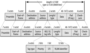
The frame starts with a "preamble." The preamble consists of a string of seven bytes of the binary pattern "10101010" to indicate that the device is about to start sending a frame. Then the eighth byte, called the "start of frame delimiter," is nearly the same as the preamble except for the last bit: "10101011". The preamble and the start of frame delimiter are not included in the frame length counter. Once you get past the preamble and start of frame delimiter, you get into the interesting parts of the Ethernet frame. Three important fields are in the frame header: the source and destination MAC addresses and the length/type field.
All Ethernet MAC addresses are 6 bytes long. Every network interface card (NIC) has a globally unique address "burned-in" to it. It is possible to override this burned-in address (BIA) to create a locally administered address (LAA). However, there are also more special-purpose MAC addresses, such as multicast and broadcast addresses. I will discuss these special-purpose addresses later in this book.
The destination MAC address is always first. This gives the network devices every possible advantage in forwarding packets as quickly as possible. Modern high-speed networking equipment is able to read the frame as it is received. Since the network usually only need to look at where the packet is going, if the destination address is first, it is often possible to start directing the frame to the appropriate destination port just from this information.
The source MAC address comes next. This is the address of the device that sent the frame. Note that it is not necessarily the originator of the packet. If the packet came from an intermediate device such as a router, then the source address will be that of the router. This address is included mostly for the benefit of the recipient device, which needs to know where to send its responses. If the return path needs to pass through a router, then the router's address needs to be here.
The third important field in the Ethernet frame header is the multipurpose "length/type" field (also called Ethertype). This 2-byte number could either be a length or a type. The only way to tell the difference is that the maximum valid length is 1500 bytes.[2] If the value in this field is less than or equal to 1500, it is interpreted as a length.
Similarly, anything larger than 1500 must be a type. Just to be absolutely certain, there is a small gap to the nearest "round" number in hexadecimal, 0600, which is 1536 in decimal. The actual values in the type field represent different protocols, and the IEEE keeps track of these values. An up-to-date list of assigned values is available online from the IEEE web site at http://standards.ieee.org/regauth/ethertype/type-pub.html. This list includes a very large number of companies that have registered particular Ethernet protocol types, although only a handful of types are commonly seen in most production LANs.
Novell reserves Ethernet types 8137 and 8138 for IPX. Type 8137 designates an older version of IPX that is not widely used anymore, while 8138 is the most typical for modern IPX installations. Apple's Ethernet protocol uses type code 809B. The Banyan Network Operating System uses 0BAD and 0BAF, and 8191 is reserved for NetBEUI, which is frequently used for PC file-sharing systems. The most common type field values are 0800, used for frames containing standard IP packets, and 0806, used for IP ARP packets.
In most LANs, IPX uses the length rather than the type. If you look at a protocol analyzer, you will probably see all of the IPX frames with a length/type value of something less than 05DC (the hex value of the decimal number 1500).
TCP/IP, on the other hand, almost universally uses the type rather than length. The reason for the difference is largely historical. The type interpretation is used by an earlier standard for defining Ethernet frames, called Ethernet II. The length interpretation, on the other hand, is the method employed by the newer IEEE 802.3 standard.
It should be obvious why it is more efficient to use the type field as a type rather than as a length. If any one protocol prefers to use its length, then that protocol has effectively trampled over 1500 possible type codes. Furthermore, it is much more efficient if the protocol stacks of both the end and network devices don't have to read into the data portion of the frame before they can figure out what type of packet it is. Not every device cares about every protocol (particularly when the packets are received as broadcasts), so knowing whether they should bother decoding any given packet is useful. But there are other benefits to this system.
For protocols that use the 802.3 standard, it is necessary to use another method for identifying the type. Using this method is done by adding Sub-Network Access Protocol (SNAP) information to the packet. SNAP is part of the LLC (Logical Link Control) sublayer of the Data Link Layer. It is defined as an extension to the 802.2 standard. The presence of a type rather than a length value in the "length/type" field automatically tells the receiving station to look for LLC information later in the packet.
This process may sound complicated, but it allows greater flexibility in the protocol. Rather than a single type field, 802.2 allows the creation of an arbitrary Protocol Data Unit (PDU), which can be used to contain a huge variety of extensions to the protocol. This LLC PDU information is tacked on to the start of the data portion of the packet, immediately after the standard Ethernet header information. In effect, it looks like another type of header, placed after the MAC header.
Also note that the 802.2 LLC sublayer is not unique to Ethernet. Exactly the same SNAP PDU that defines IPX in an Ethernet frame can be used to define IPX in a Token Ring frame.
SNAP is just one simple example of this type of a PDU. Inside the SNAP PDU is a field that defines that protocol type.
At the end of every 802.3 Ethernet frame is a 4-byte checksum called Frame Check Sequence (FCS). This checksum is a relatively simple method of ensuring that the packet was not damaged as it crossed through the network. Generally, one doesn't expect to see very many checksum errors in a stable Ethernet network. Those that are seen are usually caused by other problems, such as late collisions. However, when random electrical problems are on a link, these checksums are useful in finding them.
This checksum is calculated on the entire Ethernet frame from the Destination Address right up to the Data (and possible padding). If the payload protocol contains another checksum, it provides an extra layer of certainty. When there are checksum failures, it can also be used to investigate which layers of the protocol see the problem. For example, if the Ethernet level FCS field is good, but the TCP checksum is bad, then the problem must have existed before the packet hit this part of the network.
The same 802.3 Ethernet frame used for 10Mbps Ethernet is also used for 100Mbps, Gigabit, and 10 Gigabit Ethernet. The same MAC multicast and broadcast addresses are used by all of these standards. The use of these addresses makes life much easier for the network designer because it means that you can freely mix these different standards to fit your immediate needs.
For example, you can have Gigabit Ethernet trunks connecting your Distribution switch to your Access switches. Then you can have 100Mbps Fast Ethernet links to some workstations, and even step down to workgroup hubs of standard half-duplex 10BaseT for the less active user workstations. Throughout this complex hybrid of media types, the same Ethernet frames can be transmitted without change.
Every 6-byte Ethernet address is divided into two parts. The first three bytes represent the vendor, and the rest are allocated by that vendor in whatever method is appropriate. The first half of the address is called the vendor Organizationally Unique Identifier (OUI) value. Again, an up-to-date list of OUI values is available on-line from the IEEE at http://standards.ieee.org/regauth/oui/oui.txt.
One
of the OUI codes for Compaq is 00-80-5F. With this
OUI, they are able to define MAC addresses for their equipment by
specifying the last three octets by whatever system is most
meaningful. One example might be
00-80-5F-12-34-56.
Only the vendor who owns a particular OUI may generate MAC addresses in that range. Every device has a unique MAC address, but they are really the so-called BIA. Many devices have the capability to override the BIA with a user-defined MAC address, called an LAA. This capability can be useful if one device has to masquerade as a second device. In Chapter 3, I discussed the HSRP and VRRP protocols that use this sort of MAC address masquerading to facilitate automated fault recovery.
Some protocols, such as DECNET, can
generate MAC addresses dynamically. This generation can cause
confusion when looking at a protocol analyzer on the segment because,
for example, the MAC used for DECNET would be different from the MAC
used by the same device for TCP/IP. In the case of DECNET, this
problem is relatively easy to spot because DECNET addresses always
use an OUI value of AA-00-04.
This situation can lead to problems for network segments that have DECNET and TCP/IP operating together. Some devices confuse the two MAC addresses. For example, if a router has DECNET enabled suddenly, it may opt to use the new DECNET MAC for its IP packets as well, ignoring IP packets destined for its BIA. Whether this problem occurs depends on the router implementation.
There are two other important classes of Ethernet MAC addresses: the broadcast and multicast addresses.
A standard broadcast address of FF-FF-FF-FF-FF-FF
is used by all Ethernet protocols to indicate a packet that should be
delivered to every other device in the broadcast domain. When a
device sends out a broadcast packet, it usually either advertises
itself as a service of some kind or looks for a network resource.
A good
example of using a broadcast to look for a network resource is the IP
ARP packet. In an ARP packet, the requesting device specifies its own
IP and MAC addresses and the IP address for which it is looking. Then
it sets the Layer 2 destination to
FF-FF-FF-FF-FF-FF and sends it out. This way, the
packet gets sent to every other device in the local address range,
and hopefully the owner of the requested IP address will respond. In
some cases, a router might respond by Proxy ARP for a downstream
device. The two devices can then hold their conversation in private
without bothering everybody else on the LAN.
And a typical example of a service advertisement is the Novell Service Advertisement Protocol (SAP). In this case, the server periodically sends SAP packets to every device on the network, telling potential LAN clients about what sorts of services the server offers. The SAP may say, for example, that this server offers file-sharing services, printing, or time, database, or other application services. In a large LAN with many servers, SAP can represent a lot of traffic. I discuss IPX SAP issues in more detail in Chapter 7.
Multicast packets are intended for groups of users, but not
necessarily the entire network. To help achieve this feat, another
group of what might be called "multicast OUIs" is
defined. For example, the IP multicast standard specifies the address
range from 01-00-5E-00-00-00 to
01-00-5E-7F-FF-FF for all IP multicast traffic.
There is a simple rule for multicast MAC addresses: the lowest bit in the first octet of any multicast MAC address is always 1. The way 802.3 specifies byte ordering of information in the frame header, this is the first bit received. The IEEE has been careful to ensure that every standard vendor OUI has this bit equal to 0.
It is possible, therefore, to convert any standard vendor OUI to a
multicast OUI by simply flipping this bit from a 0 to a 1. For
example, Cisco has the OUI 00-00-0c, which allows
Cisco to define multicast MAC addresses that begin with
01-00-0c.
I talk more about multicast IP networking in Chapter 10.
Ethernet is always specified with strict distance limitations. These distance limitations are carefully calculated so that the first bit of the preamble can reach all parts of the network before the last bit of data is transmitted, even for the smallest possible frame size.
When a device wants to send a packet, it first listens to verify that nothing else is currently transmitting. This verification is called the "carrier sense" phase. If the line is quiet, it starts to send its frame. Meanwhile, another device may also want to send data, and it does the same thing. If the network is built within Ethernet specifications, the second device sees the frame coming from the first device before it has finished sending its own. It will realize that it has suffered a collision, and will send a "jamming" pattern to ensure that the first device knows that its packet has been damaged. The first device, meanwhile, has seen the start of the second device's packet, and it too sends the jamming pattern.
This procedure is normal when a collision is encountered. Then both devices wait for a random short time interval called the "backoff" interval before trying again. This time interval must be random because if both devices waited the same amount of time, then they would just collide again as soon as the backoff interval had expired. This whole system is called Carrier Sense Multiple Access/Collision Detection (CSMA/CD). It is fundamental to all multiple-access Ethernet systems.
A "late collision" means that the collision process has been followed, but that one of the devices was past the minimum frame size for the medium when it saw the colliding frame. This collision is a bad sign because it either means that the second device does not follow Ethernet rules for collision detection or that it is too far away to see the frame in time. Either way, late collisions usually indicate a serious problem because the time required to inject a whole packet into the Ethernet segment is less than the time required to have it hit the farthest point on that network. A collision can happen to a packet in flight, but the sender will not know about it, and therefore won't be able to retransmit the lost data. This is why late collisions should always be taken seriously.
There is an important difference between a collision and simply having to wait to transmit. When a device wants to send data, it first listens to the wire to see if another device is already talking. If the line is busy, it waits until the current packet is finished. After the current packet is completely sent, the device waits a standard Inter-Frame Gap Time to make sure that the line is really free before it tries to send its packet. A collision only happens if another device also sends a packet at the same time.
The critical difference is that, while a device waits to talk, the network is fully utilized. When two packets collide, no information is transmitted. I make this distinction because some devices report statistics on packets that have been delayed or "deferred," as well as packet collisions. The mere presence of either deferred packets or collisions is not a sign of problems. The packets or collisions are both perfectly normal aspects of Ethernet that we expect to see all the time. What you don't want to see is a high ratio of collisions to packets sent. This ratio is a very accurate measure of network efficiency.
Note, however, that switched full-duplex access is a completely different matter. In fact, collision detection doesn't exist in full-duplex operation. When a network segment operates in full-duplex mode, only two devices are on that segment. One of these devices is usually a switch. Because it is full-duplex, both devices can send and receive at the same time without contention, so there can never be a collision. This feature makes full-duplex much simpler to implement and gives much better performance.
In full-duplex operation, each device sends a frame whenever it has a frame to send, with two small caveats. First, a standard time interval called the Inter-Frame Gap Time must elapse after the last frame is sent and before the next one. This relatively short time period required by the protocol ensures that the start of the next frame is properly distinguished from the last one.
Note that one relatively common Ethernet problem occurs when a half-duplex device is connected to a full-duplex switch, or vice versa. This is normally not a problem, since most devices are set up by default to automatically detect and negotiate the best duplex settings. However, sometimes the negotiation process fails to work properly, particularly when the equipment comes from different vendors. It is also possible to statically configure most Ethernet equipment to use either duplex setting exclusively. This configuration represents a good solution to the problem of improper negotiation, but it also makes it possible to configure a conflict.
The problem with this particular conflict is that, in most cases, the connection still works, but the full-duplex device ignores collision information. The result is that the half-duplex device sees large numbers of late collisions.
A special addition was made to the 802.3 standard when full-duplex modes of operation became available. The problem with being able to talk all the time is that you might exceed your partner's capacity to listen. Buffers can fill up, particularly if upstream bottlenecks prevent the data from being passed along as it is received. Without collisions to offer a natural mechanism for forcing a backoff, a new mechanism had to be added to the protocol. This mechanism is the PAUSE frame.
The PAUSE frame is a short instruction that simply tells the other device that it must stop sending anything for a specified short period of time. The time interval is a number from 0 to 65,535, which measures time in units of "pause quanta." One pause quantum is the time it takes to send 512 bits. Fast Ethernet is able to transmit 100Mbps serially, so the time to transmit one bit is 0.01 μs (microseconds). The maximum total pause duration in Fast Ethernet, then, is .35 seconds.
Because Gigabit Ethernet uses 10-bit rather than 8-bit encoding at Layer 1, the maximum pause time actually drops by a little more than a factor of 10.
There are several interesting features of this PAUSE frame. It is
always sent to the multicast address
01-80-C2-00-00-01, and it is the only defined
member of a new class of MAC Control packets. Perhaps future versions
of 802.3 will require other types of control messages. In general,
the PAUSE looks like a regular 802.3 frame, except that the value in
the length/type field is 88-08. The data segment of the frame
contains the two-byte Control Opcode type, followed by the value of
the pause time variable and sufficient padding of zeros to make the
frame reach the required length. Since this is the only defined
Control message, it has a Control Opcode of 00-01.
I have already discussed hubs, bridges, and switches in earlier chapters. Here I will focus on design issues of the various options.
A hub is a way of allowing devices to share a collision domain, while a switch is a way of separating collision domains. All other things being equal, the smaller the collision domains are, the better the overall network performance will be. Clearly, if you could afford to do it, you'd rather put every single workstation on its own switch port. However, this solution is not always practical.
Much of the literature on Ethernet discusses the so-called 5-4-3 Repeater rule. This rule is at best a loose approximation of IEEE standards. It also represents a completely outdated way of looking at Ethernet segment combinations that I don't support. I favor a simpler rule, for which I'll make up the name the 1 Repeater rule. My simplified rule says that every time I use a hub, I will connect it directly to a switch. Cascading hubs and repeaters one after another is dangerous and is never necessary in a modern, well-designed network. The only time I will break my 1 Repeater rule is when I need to use transceivers that are also technically repeaters. In this case, it is acceptable to connect a hub to a switch by means of a pair of transceivers, one at each end.
In any case, I never recommend connecting one hub directly to another hub. Hubs should only connect back to the Access switches (or Distribution switches, in a very small network). Even in a small office or home network, cascading multiple hubs together results in instability and poor performance. In large networks, it has the added problem of making troubleshooting far more difficult than it needs to be.
These comments apply to both 10 and 100Mbps Ethernet configurations.
In a network of any size, manageability of Access devices becomes increasingly important. It doesn't matter whether the Access devices are hubs or switches. What matters is that the network manager can easily tell when end devices have problems. Approaching the same problem from the other direction, the network manager also needs to be able to find individual devices by MAC address wherever they are on the network.
These goals are relatively easy to achieve by just using manageable hubs and switches and having good network management software. Chapter 9 discusses how to build a manageable network in more detail. A key requirement will always be that Access devices have to be manageable.
The only place where unmanageable Access devices are acceptable is in networks too small to be managed proactively. In a home or small office network there probably will not be a dedicated system monitoring the few network devices, and the small number of devices actually makes it less necessary to monitor them. As discussed in Chapter 2, the probability of any one device failing is relatively small. It only becomes a serious issue when there are so many devices on the network that one can statistically expect to see something fail fairly often. Fault isolation in small networks is rather simple when there are very few possible failure points.
In small networks, manageable hubs and switches do not actually provide much real benefit. Since unmanageable devices are usually significantly less expensive, it makes sense to use them here. In any network large enough to warrant full-time network staff, though, it is best to have network management functionality on all network devices.
In some bridged protocols, such as some IBM LLC protocols, the number of bridge hops can become extremely important. Thus, it is important to know where all bridges in the network are. A network could have an unmanaged bridge that the network engineer may not know about.
This is the case for all of the so-called 10/100 hubs. These devices are hubs in the standard sense of the word, except that they have the added feature of being able to autosense whether the devices connecting to them are capable of 100Mbps Fast Ethernet speeds. If the device is Fast Ethernet capable, then the hub operates as a 100BaseT hub.
Obviously, it is not possible to run a hub with a mixture of 10BaseT and 100BaseT ports. The two protocols are electrically different at the physical layer. Thus, these devices are actually made up of two hubs—one for 10BaseT and the other for 100BaseT. Whenever a new device is connected to a port on this hub, it automatically senses which Ethernet standard is appropriate. In the case of NICs that are also able to operate in either mode, the autonegotiation process tries to pick the fastest speed available. There are some cases of vendor incompatibility problems in this autonegotiation process, so it is possible to get the slower connection.
When the autonegotiation process decides to use the 10BaseT standard, the hub connects the port internally to its 10BaseT hub circuitry. When it finds Fast Ethernet capability, it uses the faster 100BaseT internal hub circuits. To allow these two sides of the hub to communicate internally, a bridge contained inside the hub interconnects the two hubs at the logical link layer.
A transceiver is a specialized device used to interconnect two different physical media types. The term is just a contraction of "transmitter" and "receiver," which, unfortunately, is no longer as meaningful a name as it originally was.
Some of the earliest transceiver implementations were the devices that converted the media-independent Attachment Unit Interface (AUI) port that was common on a NIC to whatever medium was required. For example, some transceivers that converted AUI were 10Base2, 10Base5, 10BaseT, and 10BaseF. The advantage with this scheme was that users could buy a simple generic Ethernet card and use whatever type of transceiver was appropriate to their requirements.
However, with the advent of Fast Ethernet, this solution became less practical. There is a media-independent interface defined for Fast Ethernet, called simply Media Independent Interface (MII). However, this interface has not enjoyed widespread acceptance, and MII transceivers are rare and expensive. It is more common to find Fast Ethernet devices implemented with a built-in transceiver; they present only a RJ45 or a fiber optic connector.
In these cases, if you want to convert from, say, RJ45 to fiber connections, you would have to use another type of transceiver. This media conversion device is actually two transceivers in one box. It is a 100BaseT transceiver on the RJ45 side and is a 100BaseFX transceiver on the fiber optic side. Between these two transceivers is a repeater. This may sound like an academic distinction, but it can be important. Some repeaters act more like switches, since they can operate at full-duplex; but most do not.
Suppose you want to connect the 100BaseT ports on two devices, such as a trunk link, between two switches. However, these devices are physically separated by more than 100 meters—perhaps they are on different floors. You can connect them easily by using a fiber optic connection. Connect an RJ45-to-fiber Fast Ethernet transceiver to both ends and connect the fiber between the two.
In this environment, unless the two transceivers are both capable of operating at full-duplex, the trunk link must be configured as half-duplex at both ends.
Token Ring is a ring topology LAN technology with a token-passing mechanism for eliminating contention. There are actually two standards for Token Ring. It was originally developed by engineers at IBM who created the initial specification. Subsequently, the IEEE took on the responsibility of making an industry standard Token Ring specification, under the designation 802.5. There are slight differences between the two standards, but they interoperate without any issues. One of these minor differences is that the IEEE reduced the maximum number of devices on a ring from 260 to 250 for Type 1 shielded cabling. The maximum number of devices for a ring built with Category 5 unshielded twisted pair cabling (UTP) is only 72, however.
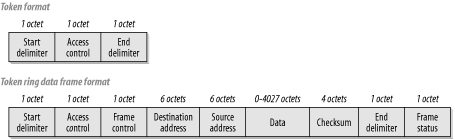
Figure 4-3 shows the formats for both an empty token and a frame that carries user data. Several features are remarkably similar to Ethernet and some are quite different. For example, the maximum Ethernet frame is 1518 octets long, while the maximum Token Ring frame size can be as much as 4550 octets in a 4Mbps ring, or 18,200 for a 16Mbps ring. In general, the Token Ring frame size is governed by the ring's hold-time parameter, which governs how long any one device is permitted to have the token.
Both Ethernet and Token Ring use 6-byte addresses. This fact makes bridging between the two much easier. However, there is one significant twist. Token Ring orders its bytes so that the most significant bit comes first, while Ethernet does exactly the opposite. If you bridge Ethernet and Token Ring segments together, you have to translate the addresses from one format to the other by changing the bit ordering.
A quick side note on the subject of Ethernet to Token Ring bridging is that there are in fact two different options for running LLC2 on Ethernet. The most common method is to simply use 802.3 format frames. The second option that appears in some installations is the so-called 80d5 format. This strange name refers to the Ethernet type code for the Ethernet II style frames. I have seen some overly helpful LLC2 server software that uses both frame types. This software tends to cause serious confusion on the bridge and should be avoided.
In general, bridging works well between Ethernet and Token Ring networks, but it is important to be careful of Maximum Transmission Unit (MTU) and watch out for these address translation issues. This warning implies, in turn, that it is possible to create a bridge between two Token Ring segments through an intermediate Fast or Gigabit Ethernet segment. If this is the goal, it would usually be more practical to use a TCP/IP tunnel protocol such as DLSw. This protocol would then allow the Token Ring MTU to be preserved through the Ethernet leg of the connection.
There are two common standards for Token Ring; one operates at 4Mbps and the other at 16Mbps. A high-speed standard also operates at 100Mbps. But, unlike the 4 and 16Mbps standards, the 100Mbps version has not seen widespread use to date.
In most cases, running the same equipment at either 4 or 16Mbps is possible. This possibility is useful, since it allows the network to use the lowest common technology. But there is an unfortunate converse to this property: once a ring has started operating at either speed, introducing a new device at the other speed can cause serious problems for the entire ring.
The token in Token Ring refers to the way that the ring avoids packet collision problems. There is a simple token packet that contains no user information. This packet is passed from station to station around the ring from an upstream to downstream neighbor. If a device has something to send, it waits until it gets the token. Then it replaces the token packet with a data packet, which it sends to its downstream neighbor instead of the token. The first two fields of this data packet look similar to the original token packet, except for one bit (the token bit) that indicates that data will follow.
This device then continues to transmit data until it either runs out of data to send or until it sends a predefined maximum number of bytes. The data can be sent either as one packet or it can be broken up into several separate packets, which can be useful if the device is talking to many other devices. Once it is done talking, it places a new token on the ring so that other devices will have an opportunity to talk as well. This method ensures that every device gets to participate fairly.
The packets that are sent this way all pass from the sender to its downstream neighbor, which forwards them on to the next downstream neighbor, and so forth, until they reach all the way back around the ring to the original sender. The sender is then responsible for removing the frames from the ring (which is called "stripping"). Once these frames are removed from the ring, the sender replaces a token onto the ring so the next device can talk.
Another interesting feature that is available in the 16Mbps Token Ring (but not in the 4Mbps standard) is Early Token Release (ETR). In this case, the sender doesn't wait until it has seen its own frames finish circulating around the ring. Instead, it puts the token back onto the ring for the next device as soon as it has finished its transmission. This placement makes the ring much more efficient. What's particularly useful about ETR is that not all devices on the ring need to support it. In fact, it should be fairly obvious that the whole ring benefits from improved throughput if even a few devices can do this.
The most common problem that arises in Token Ring topologies is a broken ring. If, for whatever reason, the ring is not closed, then the packets never get back to their starting point. As I just described, the normal token-release mechanism depends on the source device receiving the frames it has sent before it passes the empty token along for another device to use. A broken ring is a serious problem.
The ring deals with a break by sending around a beacon packet. The device that is immediately downstream from the break alerts the rest of the ring by sending this special type of frame. The beacon frame contains the Layer 2 MAC address of the upstream neighbor that has lost its connection. In this way the failure domain, the area in which the break has occurred, is identified. This identification allows the ring to go into its reconfiguration procedure.
A particular device on the ring is designated as the ring monitor. This device is responsible for putting new tokens onto the ring when they are lost. In a broken ring situation, the monitor device is able to keep communication working. However, this situation is considerably less efficient than having a properly closed ring.
Token Ring has, in general, seen significantly less industry acceptance than Ethernet, despite having some useful advantages. There are important exceptions, particularly in mainframe environments, where Token Ring is more popular, but Ethernet is definitely more popular. With the advent of higher speed versions of 802.3, the industry preference for Ethernet appears to be growing.
The main reason for this gap in acceptance is simply the implementation cost. Token Ring hubs and switches cost more than Ethernet hubs and switches. However, the largest portion of the cost difference comes from the higher prices of Token Ring NICs and the cost of the Token Ring chipsets used by these cards.
The development of 100Mbps Fast Ethernet finally eliminated the bandwidth advantages of Token Ring. By the time the new 100Mbps Token Ring devices were available, Gigabit Ethernet was also coming out. Although Token Ring has not reached any theoretical limitations, it seems unlikely that a Gigabit Token Ring standard will be available before the 10 Gigabit Ethernet makes it obsolete.
The result is that Token Ring tends to be used primarily in organizations with large legacy mainframe environments that make extensive use of Token Ring and protocols such as LLC2. In organizations with modern mainframes, there is a trend toward adopting TCP/IP as the protocol of preference and toward the installation of Gigabit Ethernet modules into the mainframes or their front-end processors.
One of the most popular methods for connecting devices to a Token Ring is the Multistation Access Unit (MAU). This unit is traditionally an unmanaged device, with the classic example being the IBM 8228. The 8228 requires no external power. Rather, the individual end devices provide the power for the MAU to operate. When no device is connected to a port, a relay switch disconnects it from the ring. Then, when a device connects, it provides power to this relay and is inserted into the ring electrically.
At either end of the MAU are ports labeled "Ring-In" (RI) and "Ring-Out" (RO). These ports are provided to allow several MAU devices to be chained together into a larger ring. The RI port from one MAU is connected to the RO port of the next, and so on around the ring until the RO port of the first MAU is connected back to the RI port of the last to close the ring. These RI and RO ports are not equipped with the same sort of relay switching as the regular device ports, so they can only be used for interconnecting MAUs.
The IBM 8228 uses IBM UDC connectors (also called "hermaphroditic" connectors because they are both male and female), which are usually used with IBM Type 1 shielded cabling. However, there are also RJ45 MAU units from both IBM and other manufacturers. Generally, the RJ45 units require external power like Ethernet hubs. Other than this, no real functional differences exist between these two types of MAUs.
A managed Token Ring hub is also sometimes called a Controlled Access Unit (CAU). This hub generally operates in a similar manner, except that it becomes possible to monitor utilization and error statistics on individual ports, and activate or deactivate ports individually. Some of these hubs have the ability to assign individual ports to different physical rings internally, similar to an Ethernet VLAN.
Token Ring switching is really nothing more than Token Ring bridging, just like in Ethernet. Also as in Ethernet networks, Token Ring switches are becoming a popular method of connecting important end devices to the network. In effect, the switch becomes a multiport bridge that interconnects a large number of different rings.
Typically, source-route bridging is used in Token Ring networks. Besides the simple bridging functions that allow a separate token on each port, source-route bridging allows devices to find the optimal path through the network. They find this path by means of Routing Information Field (RIF) data that is added to packets as they travel through the network.
When a device wants to find a particular MAC somewhere on the network, it sends out an "explorer" packet. This broadcast frame finds its way throughout the whole network, hopefully to the desired destination. Along the way, the explorer packet picks the RIF information that describes the path it took. The destination device then responds using the shortest path.
As with Ethernet switches, Token Ring switches are able to implement VLANs. This is done in exactly the same way as on Ethernet. All ports that are part of the same VLAN are bridged. Meanwhile, distinct VLANs do not communicate directly, but must instead communicate through a router.
Each port on a Token Ring switch is a distinct ring, regardless of VLAN membership. This situation is analogous to Ethernet, where each port is a distinct collision domain, regardless of VLAN membership. Two ports that are members of the same VLAN have a bridge connecting them, while ports from distinct VLANs do not. As in Ethernet, when individual end devices are connected to a switch directly, it is possible to use a full-duplex version of the protocol allowing simultaneous sending and receiving of packets. This full-duplex version of Token Ring requires that the end device have Direct Token Ring (DTR) capabilities. DTR is not part of the 802.5 standard, but is nonetheless a widely implemented feature.
At Layer 2, Gigabit Ethernet looks exactly like 10Mbps and 100Mbps Ethernet. They all apply the same 802.3 standards for framing and addressing. This similarity is convenient because it means that interconnecting Ethernet segments of these different types is simple. At Layer 1, however, the electrical signaling standards for Gigabit Ethernet are completely different.
The first set of Gigabit IEEE standards was specifically geared toward a fiber optic implementation. Naturally, the first Gigabit devices on the market all used fiber optic connectors. However, shortly thereafter, an addendum was released that included specifications for running Gigabit Ethernet over Category 5 unshielded twisted pair (UTP) cabling. Gigabit Ethernet over Category 5 cabling is called 1000BaseT. It allows for distances of up to 100 meters, similar to the 100BaseT and 10BaseT standards. This is convenient because it means that Gigabit Ethernet should, in principle, be able to operate over the same cable plant as an existing Fast Ethernet implementation.
However, there is one important caveat to this Category 5 implementation of Gigabit Ethernet, as I discuss later in this chapter. The original specifications for Category 5 cable plants did not specify signal reflection properties of connectors, which turn out to be important in Gigabit. Thus, older Category 5 cabling may not work properly with Gigabit Ethernet.
The physical layer differences between even fiber optic implementations of Fast Ethernet and Gigabit Ethernet go well beyond merely changing the clock rate. The most important issue is the use of 8B10B encoding. At its lowest level, Gigabit Ethernet uses a 10-bit byte; at these extremely high speeds, it can be difficult to accurately distinguish between bits. Thus, 10-bit patterns have been selected to represent the 8-bit octets. The specific 10-bit patterns are chosen for their transmission reliability. There is 25% of extra overhead in encoding this way, but the improvement in reliability compensates for this additional overhead.
To make implementation details easier, the Gigabit Ethernet group has defined a natural transition point in their protocol stack called the Gigabit Media Independent Interface (GMII). This sublayer is similar in concept to the Fast Ethernet MII and the standard Ethernet AUI interface. Each case specifies a point that is technically in the middle of Layer 1. Everything above this point is generic to all different implementations of the protocol. This way, only the hardware and the protocols below the dividing point need to change when a new physical layer is defined.
Most Gigabit Ethernet hardware uses either a physical fiber optic or an RJ45 connector. However, it is possible to implement a Gigabit Ethernet interface on a device using a generic GMII connector. Then the network designer could simply connect the appropriate GMII transceiver.
Now that Gigabit Ethernet is available over Category 5 cabling, putting Gigabit NICs into servers and workstations has become technically viable. The market is also already seeing price competition between NIC vendors, which drives down the costs of running Gigabit to the desktop.
I recommend using full-duplex switched connections for connecting end devices directly to Gigabit Ethernet networks; there would be little real advantage to running a shared half-duplex Gigabit network over running a switched full-duplex Fast Ethernet network. In any Ethernet environment with several devices sharing a collision domain, the effective throughput is typically 30 to 40% of the total capacity, so you can expect to get something on the order of 300-400Mbps total aggregate capacity out of a shared Gigabit hub. Each individual device on this hub would get some small fraction of this total on average. So, for a small network with 5 Gigabit devices sharing a hub, you would expect each device to have access to an average of 60-80Mbps. The peaks for each device are, of course, much higher than this, but it is reasonable to expect that devices being considered for Gigabit Accesses will be heavily used—at least in the near future.
One can already achieve a higher average utilization using simple switched Fast Ethernet. Because the cost of Fast Ethernet is still much lower than Gigabit Ethernet for both the NICs and network devices, it is not cost-effective to use Gigabit Ethernet this way.
Consequently, if an organization has end devices that are important enough and used heavily enough to warrant connecting to the network at Gigabit speeds, it makes sense to use full-duplex switched connections. As it turns out, the marketplace appears to have already made this decision, as Gigabit hubs are not made by any major vendor, while there are several vendors selling Gigabit switches.
In a unanimous decision, the IEEE 802.3 committee on 10 Gigabit Ethernet has decided not to bother implementing anything but a full-duplex version of the new protocol. So, although the standard is not yet complete as of the time of writing this book, we already know a few things about what it will look like. We know that there will be no such thing as a 10 Gigabit hub and that there will be no defined collision mechanism. This is a good thing. It seems that the market has already decided that the Gigabit standard is most useful in a switched full-duplex mode. Most organizations using Gigabit Ethernet use it as a trunk or backbone technology or attach only a small number of important servers at Gigabit speeds.
It is important to remember that this is similar to how Fast Ethernet started out. In the future, some organizations may have large numbers of Gigabit end user devices.
Adoption of the new high-speed protocol as a standard for end devices has been a little slow, mostly because of the time lag between the fiber and copper standards for delivering the medium. However, now that a version of Gigabit Ethernet that works over Category 5 cabling has been finalized and hardware vendors are releasing equipment based on the standard, there should be more use of the high-speed protocol.
The lack of a half-duplex version for 10 Gigabit Ethernet means that, when it is available, it will probably not be quickly extended to the desktop. It is not yet completely clear what sort of twisted pair copper cabling the 10 Gigabit standard will eventually use. Category 5 cable is certainly reaching its limitations with Gigabit Ethernet. However, the emerging Category 6 standard has not yet been fully embraced by the 10 Gigabit working groups, which are naturally focused on optical fiber implementations.
The bottom line is that it will be many years before you can expect to see 10 Gigabit Ethernet extended to the desktop. At the very least it will require new cable plants for most organizations, unless they happen to have optical fiber running to their desks.
I envision Gigabit and 10 Gigabit Ethernet as backbone and trunk technologies. Given the trunk aggregation rules discussed in Chapter 3, it is clear that if an organization makes extensive use of Fast Ethernet today, then it needs an inexpensive fast trunk technology. These new Gigabit and 10 Gigabit standards are ideally suited to this purpose.
One of the most positive features of Gigabit Ethernet trunks is their ability to use a common 802.3 framing throughout all levels of the network. This is important because the same VLAN tags and MAC addresses are shared throughout any Distribution Area. You don't want to have to rewrite or tunnel these pieces of information for three reasons.
First, each step introduces latency. Second, you sometimes want to put a protocol analyzer on a trunk to see what passes through it. If you can't readily distinguish the VLAN associated with a frame and if you can't easily identify the source and destination devices, it can be difficult to tell if you have a problem. Most modern protocol analyzers are able to read into a packet to help with this problem, but it can still be difficult to see what's going on, depending on the types of tunneling employed.
The third advantage to using the same 802.3 frame at each stage of a packet's journey through the network is that it ensures consistency in the treatment of its priority. As I mentioned previously, the Class of Service (CoS) field is associated with the VLAN tag. Knowing this allows the network to have a consistent logical identifier for the prioritization scheme to use at each hop up until the packet hits a router. At the router, of course, a higher layer identifier (such as the IP TOS or DSCP field) has to carry the information, since the packet will lose its Layer 2 information as it crosses through the router.
I consider Gigabit and 10 Gigabit Ethernet naturally suited to trunk links in large-scale LANs. Interestingly, much of the current discussion regarding these standards involves their use in larger Metropolitan Area Network (MANs) and Wide Area Networks (WANs) as well. As it is currently common to see MAN and WAN networks implemented using ATM and delivered to the customer premises as an Ethernet or Fast Ethernet port, it does seem natural to extend this delivery to Gigabit speeds as well. Certainly this extension would give efficient near-capacity access to the current highest-speed ATM link technologies. It might turn out to be a good low-cost delivery mechanism for these links. However, any more detailed discussion of WAN technologies or speculation on yet unwritten standards is beyond the scope of this book.
At one time, ATM looked like it was going to take over the entire networking world. With highly successful WAN implementations coupled with LAN Emulation (LANE), it looked like ATM would be able to provide inexpensive end-to-end solutions. However, the emergence of Gigabit and 10 Gigabit Ethernet standards appear to make this less likely. Implementing a LAN with end-to-end 802.3 framing is certainly easier than building a distinct Distribution and Core level network that merely emulates 802.3 at the edges of the Access Level.
However, for WAN carriers, particularly telephone companies that are concerned with carrying voice, data, and perhaps even video information over the same network, ATM is still the natural choice. There is no 802.3 implementation that is as efficient over long distances as ATM. The small ATM cell size makes it perfect for carrying real-time voice and video information with minimal latency.
There are two real problems with using ATM in a large LAN. The first problem is the additional overhead of the various LAN Emulation servers required for either LANE or Multiple Protocol Over ATM (MPOA) implementations. The second serious drawback is the high cost-to-bandwidth ratios. The fastest commonly available ATM modules for LAN switching are OC-12, and some vendors also make OC-48 modules. The wire speed for OC-12 is only 622Mbps, OC-48 runs at 2.48Gbps (2488Mbps), as compared to 1000Mbps for Gigabit Ethernet. The OC-12 modules are generally more expensive than Gigabit Ethernet and offer less bandwidth. Currently, only fiber optic implementations are available for either OC-12 or OC-48, which is generally more expensive than twisted pair implementations of Gigabit Ethernet.
OC-192, which has a wire speed of 10Gbps, is still a viable option for high-speed LAN backbones if speed is the primary objective. With 10 Gigabit Ethernet just around the corner, it is unlikely that the additional expense of implementing an ATM LAN backbone will be justified in the long run. Furthermore, current OC-192 products tend to be deliberately targeted toward WAN and MAN service providers, so support for LAN Emulation implementations is weak.
If you want high-speed LAN infrastructure, ATM is probably not the most cost-effective way to get it. However, because many sites still have some ATM infrastructure, and because some networks require the highest speeds available, I will spend a little bit of time discussing ATM's properties.
ATM uses a completely different design philosophy than Ethernet or Token Ring. An ATM network is composed of a number of switches interconnected by high-speed (usually fiber optic) links. The native ATM packet is called a "cell." Each cell consists of a 5-octet header and a 48-octet payload, as shown in Figure 4-4. The small size of these cells ensures that latency passing through the network is minimized. This minimization is critical for real-time communications such as voice or video. Furthermore, by making every cell exactly the same size, the work of the switches becomes much easier. All cells are switched according to the information in the cell header. Once a connection is established, the switch always knows exactly what the bit offset is to find every piece of information it needs to do this switching, thereby minimizing the amount of work it has to do.
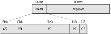
The key to taking advantage of these efficiencies lies in the creation of Virtual Circuits (VCs)through the ATM network. A VC can be either a Permanent Virtual Circuit (PVC) or a temporary Switch Virtual Circuit (SVC). Once a VC is created, however, the end point switches know it by a Virtual Path Identifier (VPI) and a Virtual Channel Identifier (VCI). Each Virtual Path can theoretically contain as many as 65,536 Virtual Channels. A switch can address up to 256 different Virtual Paths.
PVCs are commonly used in WAN applications, allowing the virtual creation of high-speed long-haul links through existing ATM clouds. SVCs, on the other hand, have many different sorts of applications and are frequently seen in LANE-type situations.
Figure 4-4 shows a User-Network Interface (UNI) cell. This cell is what one would most commonly expect to see at the edges of a LAN, as it is used to connect between a switch and an end device (in this case, the end device could also be a router). There is, however, another cell format called Network-Network Interface (NNI) that is used to connect switches to one another. For private networks, there is another cell format defined for Private Network-Network Interface (PNNI) as well. However, describing switch-to-switch interactions in ATM networks is beyond the scope of this book.
ATM was designed as a fast, scalable, low-latency network protocol for transporting a variety of real-time data types. One of the most common applications is found in Telephony applications. Most modern telephone networks are now built using ATM fabric because of its efficient resource utilization and relatively low cost for high-speed long-distance links. It is also commonly used in wide-area data networks for the same reasons. However, in both cases, the network service provider frequently hides the ATM network from the customer and presents some sort of emulated service instead. For example, most modern Frame Relay WAN links are actually provided over an ATM network fabric.
Several different so-called Adaptation Layers are defined for ATM. Data communication uses ATM Adaptation Layer 5 (AAL5), which defines how the ATM cell payload is used to carry packet-type data. Similarly, AAL1 is used for emulating legacy circuit technology such as T1 or E1 circuits with Constant Bit Rate (CBR) Quality of Service characteristics. AAL2 is intended for transmitting packetized audio and video information with a variable bit rate (VBR). AAL3 and 4 are generally merged as AAL3/4, which is similar to AAL2, except that it includes no facility for keeping timing information intact across the network.
Quality of Service is built into the ATM protocol. Several standard methods for delivering packets are defined according to how much bandwidth needs to be reserved for each Virtual Channel or Path. This is called the bit rate, so you can have CBR, in which no bursting is assumed. The channel is always run as if it contains a steady stream of data. Running it this way is useful for emulating analog services. However, it is wasteful of network bandwidth if you are able to packetize your data—allowing bursts when you need them and letting the network go quiet when you don't need them. To allow these options, ATM defines VBR and UBR.
VBR has two options, real-time and non-real-time. The real-time option is generally used for applications that are particularly sensitive to latency, such as video. The non-real time option is more frequently used for data communications. UBR, on the other hand, handles all packets on a "best efforts basis."
The last category is Available Bit Rate (ABR). ABR is an adaptive system in which the end nodes are able to take advantage of extra bandwidth. When the network is short of resources, it can ask the end devices to slow down. This method of handling bandwidth resources is often used in LANE applications.
ATM is typically used in a LAN in one of four different ways. The earliest ATM LAN applications were usually built using the standard defined in IETF RFC 1483. This standard specifies a method for bridging standard LAN protocols such as Ethernet and Token Ring over an ATM network. Usually, this type of system is used with a set of ATM PVC links. The standard needs only to define how packets from the various LAN protocols are chopped up into small ATM cells and carried through the network.
RFC 1483 is an effective way of extending a LAN bridge across a WAN, and it is also useful as a LAN backbone. If you have a LAN that has an ATM-based Core or Distribution level, then it is simple to use RFC 1483 encapsulation for your various trunk links. All you need to do is to build a set of ATM PVC links between the various Distribution switches and use these PVCs as the trunks.
Some vendors of ATM equipment have clever proprietary systems for maintaining PVCs through an ATM network. These systems allow the ATM network to contain a number of different physical paths between the two end points. When a network link or node fails, then the other ATM switches detect the failure and reroute the PVCs through another physical path. Thus, rerouting provides excellent fault tolerance capabilities.
Another common early technique for using ATM in the LAN is defined in RFC 1577 and updated in RFC 2225. This technique is called "Classical IP and ARP over ATM." Classical IP provided an effective method for connecting end devices to an ATM network directly. But it has the serious drawback that it is specific to the IP protocol. Thus, it does not work with any other common LAN protocols such as IPX or NetBEUI. In effect, it views ATM as just another Layer 2 protocol, similar to Ethernet or Token Ring. As such, it has to use a new form of ARP, called ATMARP, to allow ATM-attached IP devices to find one another.
ATMARP is handled by the creation of a new server. Since ATM is always connection-based, and you don't necessarily want to create a lot of VCs every time you need a physical address, an ARP cache server with a well-known ATM address is included in each IP subnet area.
Because of the high cost per interface of using ATM, most installations using RFC 1577 do so only on a handful of important servers. These servers are then directly connected to ATM switches. This connection lets these servers tap directly into the LAN backbone. However, Gigabit Ethernet is currently a more natural and cost-effective way to implement this sort of high-speed server farm. Thus, Classical IP is becoming less common than it once was.
The remaining two ATM LAN systems are closely related. The first is LANE, and the second Multiple Protocol Over ATM (MPOA). MPOA contains a set of improvements and upgrades over LANE, but otherwise the two systems are functionally similar. In both cases, end devices are connected to standard LAN equipment, usually Ethernet or Token Ring. The LAN switches include ATM connections as well as LAN connections. The trunk links are made up of ATM connections between these LAN switches.
Rather than using VLANs and 802.1Q tagging, ATM LANE and MPOA use Emulated LANs (ELANs). This service allows the ATM network to bridge the standard Ethernet or Token Ring LAN traffic, creating connections as required.
The biggest difference between an Ethernet or Token Ring LAN and an ATM network is that the ATM network is connection oriented. This means that every conversation passing through an ATM network must use a virtual circuit. This virtual circuit can be either permanent (PVC) or temporary (SVC), but a connection must be built and maintained for the conversation to work. Ethernet and Token Ring, on the other hand, allow any device to communicate with any other device whenever they feel like it. All that is needed is the destination device's MAC address, and a packet can be sent to it directly.
Emulating a LAN using ATM requires sophisticated call setup procedures. The ATM network has to be able to keep track of all LAN MAC addresses and use this information to quickly create new SVCs between the appropriate switches whenever two devices want to talk. The ATM network also has to monitor these SVCs to make sure that the calls are torn down when they are no longer required.
Each device that connects directly to the ATM cloud is called LAN Emulation Client (LEC). The LEC is usually a LAN switch with an ATM interface, but it could be a native ATM device such as a server with an ATM interface. Each LEC can talk to any other LEC that is in the same ELAN.
Every ELAN must have two special servers called the a LAN Emulation Server (LES) and Broadcast and Unknown Server (BUS). As the name suggests, the BUS is responsible for handling the LAN broadcasts and for resolving unknown MAC addresses. The LES is what the LEC talks to first whenever it wants to start a conversation with another LEC. The LES then begins the process of setting up the SVC required for the conversation.
There is also a universal server called the LAN Emulation Configuration Server (LECS) that is common to all ELANs on the entire ATM network. This server keeps track of which ELAN each LEC belongs to. Every time a new LEC is activated, it has to ask the LECS for information about its ELAN and for help in finding the appropriate LES and BUS servers. As such, the LECS is a critical device to the entire network, but it actually is not used very often.
Most LANE and MPOA implementations offer clever methods for switching to redundant backup LES, BUS, and LECS servers. Usually, these servers are themselves contained in the management modules of the ATM switches. These servers are critical network devices, so it is wise to have them housed inside of network equipment. Whatever the physical configuration, they absolutely must have fully redundant backups capable of restoring all functionality quickly in the event of a failure. In one LANE installation I know of, a LECS failure required several minutes to switch over to the backup. Although the network was still operational during this period, a failure that occurred during a peak period, such as the start of the business day when calls are first being set up throughout the network, would be disastrous.
There is significant additional complexity involved in building redundancy for LES, BUS, and LECS servers. The network designer must ensure that failover from primary to backup is acceptably fast. This issue has proven to be a serious hidden problem with many ATM-based LANs, and is yet another reason for using Gigabit Ethernet instead.
Fiber Distributed Data Interface (FDDI), like ATM, was once a good choice for LAN backbones because of higher available speeds. But, just as with ATM, it appears to have been supplanted by the advent of high-speed Ethernet technology. In general, I don't advise implementing new FDDI networks without a compelling and unique requirement. However, it is important to understand FDDI because many networks still contain FDDI elements. If a network designer wants to upgrade a LAN infrastructure that contains FDDI components, she needs to understand how it works. It is likely that legacy FDDI installations are in critical parts of the network.
FDDI is a fiber optic-based networking protocol that uses two counter-rotating rings. I discussed it briefly in the previous chapter and showed how its clever fault tolerance system works. Since the protocol allows data transmission at 100Mbps, it was once useful as a network backbone. It has also been used effectively to create server farms close to the network Core Level. However, Fast Ethernet and 100Mbps Token Ring have effectively killed FDDI, and Gigabit Ethernet has rendered it obsolete. We still sometimes see legacy FDDI equipment supporting server farms. There are also some older implementations of network disk arrays and server clusters using FDDI that are still in operation.
You can build an FDDI network in two ways. The simple method is to connect fiber patch cords directly between the various ring components. Each device connects to the next, all the way around the ring. It is also possible to use an FDDI switch and construct a star topology. In this latter case, the ring becomes naturally full-duplex and closely resembles a switched Token Ring construction. Of course, it is possible to combine the two approaches, using the central switch as a multiport FDDI bridge.
Perhaps the simplest way to execute a phased removal of an FDDI backbone is to first bridge the FDDI ring to a Gigabit Ethernet switch. Then the FDDI devices can be migrated to the Ethernet switch one at a time. This way, there is no need to readdress the devices. This is important particularly in the case of server farms because readdressing servers may require changing configurations on a potentially large number of client devices.
Over the last few years, wireless networking has seen a huge increase in public acceptance and in use. It is still considerably more expensive, less reliable, and slower than conventional wire-based networks. However, in many cases, wireless is the most convenient method for delivering network services.
Two main standards are currently used for wireless local area communications: 802.11 and Bluetooth. In their most popular current implementations, both protocols use the 2.4 GHz ISM and 5 GHz UNII bands. (ISM stands for Industrial, Scientific, and Medical, and UNII for Unlicensed National Information Infrastructure.) These bands are reserved sets of frequencies that can be used without a license.
Despite having the same frequencies and similar throughput capabilities, these two protocols are not compatible with one another. Thus, it is important to understand the strengths and weaknesses of both.
Bluetooth (whose underlying protocol is currently being standardized by the IEEE under the 802.15 designation) was created as a wireless method for replacing serial, parallel, and USB-type cables. It also includes a LAN specification, but even this specification is based on an underlying serial cable emulation. Thus, the LAN links created with Bluetooth always use point-to-point protocol (PPP), which is a logical link protocol frequently used over modem-type links.
The 802.11 standard, on the other hand, is intended purely as a wireless LAN protocol. As such, its logical link protocol is similar to Ethernet. In fact, it uses Carrier Sense Multiple Access/Collision Avoidance (CSMA/CA), as opposed to Ethernet's CSMA/CD, avoiding collisions because the radio medium does not allow for reliable collision detection.
In general, the topology of a wireless LAN involves a number of wireless devices connecting to a central Access point device. It is also possible to build an ad hoc peer-to-peer network. However, this book is about large-scale LANs, so it is most concerned with how this sort of technology would be used in such a LAN.
Figure 4-5 shows how a wireless LAN might work in the context of a larger network. Every device taking part in the wireless network has its own radio receiver and transmitter built into it. It uses this radio to connect to an Access point device. The Access point is effectively a wireless hub. In fact, in many ways, it behaves exactly like an Ethernet hub.
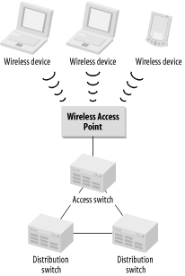
Like a hub, the Access point provides a central connection point. Also like a hub, it allows all connecting devices to share a common pool of network bandwidth. The more devices you connect to a single Access point, the smaller the share of the bandwidth each receives. This is one of the two important considerations in deciding how many Access points will be required. The other important question is how much physical area must be covered.
Before building a wireless LAN, the first question is what the wireless network will actually be used for. Will it be used to deliver standard LAN services to stationary devices, such as desks or factory assembly line stations? This might be the case because traditional LAN cabling can be awkward, expensive, or dangerous to deliver in some settings. Another place where wireless technology is useful is in highly mobile networks. For example, it might be necessary to communicate with a mobile robotic device that could be anywhere on a factory floor. Or, people might be walking around the floor of a warehouse with laptop computers for inventory checking.
The mobility of the wireless devices turns out to be extremely important. Since the greatest distance one can cover with a wireless LAN is about 100 meters, it is often necessary to have several different Access points throughout the work area and to allow devices to "roam" from one area to another. In 802.11, the area served by each Access point is called a Basic Service Set (BSS). The collection of BSS "cells" is called an Extended Service Set (ESS). These concepts are illustrated in Figure 4-6.
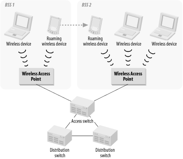
Roaming is a key concept in wireless communications and is mentioned in the 802.11 specification. However, the specification does not include standards for roaming protocols that allow devices to freely move from one BSS to another or from one ESS to another. The only way to accomplish this movement with current technology is by means of vendor proprietary roaming protocols and software. If roaming is a requirement, then it is important to ensure that all of the wireless communications equipment comes from the same vendor (to ensure interoperability).
It is possible to use either Bluetooth or 802.11 to construct a wireless LAN replacement. In general, 802.11 is the better choice for several reasons. First, Bluetooth devices generally operate at much lower power, and consequently have less range. Typical ranges quoted by manufacturers are 10 meters, compared with 100 meters for 802.11. Second, the nominal throughput with an 802.11 system is generally much better than for Bluetooth. Bluetooth LAN bandwidths are typically between 1 and 2Mbps, the same as the original 802.11 systems. However, the newer 802.11b specification allows speeds of up to 11Mbps, and 802.11a can run at over 70Mbps.
Furthermore, because Bluetooth is intended primarily as a way of replacing short cables to peripheral devices, these bandwidths are completely adequate and appropriate to this purpose. Thus, we will probably see future development of still higher-speed versions of 802.11 than for Bluetooth. However, just as with the upgrade from 100Mbps to 1000Mbps Ethernet, each new 802.11 specification will likely have physical layers that are different from previous versions. Indeed, this is already the case with the upgrade to 802.11b. As with these 802.3 examples, upgrading to the newer standard is usually relatively easy to accomplish, while switching from one standard to another (for example, Token Ring to Ethernet or, worse still, ATM to Gigabit Ethernet) can be costly and difficult.
Another new version of 802.11, called 802.11a, operates on the 5 GHz band. The 5 GHz band has a larger range of frequencies available than does the 2.4 GHz band. This fact, coupled with innovative physical coding schemes, means that 802.11a LANs will have bandwidths of at least 54Mbps. One vendor even claims to have a dual-channel mode that will operate at a theoretical maximum bandwidth of 108Mbps, although more conservative estimates say that it can deliver 72Mbps. At the time of the writing of this book there are not yet any commercial products using this technology, but they are expected shortly.
Finally, there is the issue of security in comparing the 802.11 and Bluetooth wireless systems. Because of the shorter ranges and the typical sorts of applications, Bluetooth does not actually require as much sophisticated security as does 802.11. In a true wireless LAN with larger ranges of operation and the potential for much more sensitive applications, security becomes extremely important. For this reason, 802.11 includes a specification for Wired Equivalent Privacy (WEP).
Unfortunately, a group from Berkeley recently analyzed the actual cryptographic properties of WEP and found it badly wanting.[3] In their report, they made several key recommendations for improving 802.11 security and included some network design ideas for limiting an organization's exposure.
First, a little bit of background is necessary. WEP is an optional method for implementing security in a wireless LAN. It can be turned on or off by the network administrator. When it is activated, every packet sent through the wireless medium is encrypted using an RC4 keystream. RC4 is a method of creating long, pseudorandom sequences of characters, and it is generally considered highly secure.
In 802.11, a common starting string (called the Initial Vector) is known by all end devices and by the central Access point. In fact, implementing an 802.11 network with a different Initial Vector (IV) for every device is possible, but not commonly done. The problem is that several types of attacks, which I will not describe here, can allow some or all the packets encrypted this way to be decrypted. The longer an attacker listens to the network, the better the decryption becomes.
This attack is not trivial. It requires a deliberate and concerted effort over the course of a few days to get enough information to decrypt all of the packets sent over a wireless LAN reliably. However, it is possible to do it, and it would be very difficult, if not impossible, to detect the intrusion. As network designers, we must take the possibility seriously.
Furthermore, the attacks described in the article are not all purely passive "listening" attacks. It is also possible to circumvent Access security in WEP and connect devices to the 802.11 network. Since the LAN is wireless, people in the building across the street could potentially gain active access to your corporate network without ever leaving their office.
There are two ways to approach these security problems. You can either wait until the WEP improvements mentioned in the article have been adopted and implemented, or you can consider the wireless LAN insecure and not trustworthy from the outset. It all depends on how urgent the requirement for wireless communications is to the organization. If you can wait for the protocol improvements, it would probably be better to do so.
If it is necessary to build a wireless portion to a corporate LAN, then the most secure way of doing so with current technology is to put the actual Access point on the outside of a firewall, similar to how Internet connections are made. The article mentioned previously recommends putting the wireless Access point outside of the Internet firewall, but this solution is not ideal because it potentially exposes workstations and the wireless Access point itself to Internet-based attacks. Furthermore, it presents IP addressing problems to organizations that do not possess large ranges of registered addresses. A better solution is to implement the wireless Access point behind a separate firewall.
With the Access point secured in this way, you then need to make the individual wireless connections secure through the firewall to the interior of the network. Making such selections secure is readily accomplished using standard Virtual Private Network (VPN) technology. Since VPN cryptography has been around for several years, it has finally reached a point at which it is relatively secure against all but the most concerted brute force attacks.
Figure 4-7 shows how wireless security might work. This drawing shows two distinct firewalls, one for the public Internet and the other for general untrusted devices. Many organizations have connections to external vendors and information suppliers. The information supplied by these vendors is business critical, but legitimate security concerns about exposing the internal network to external networks still exist. Thus, these external networks are called "untrusted," although a better term might be "semitrusted." This is an appropriate location for the wireless LAN connection.
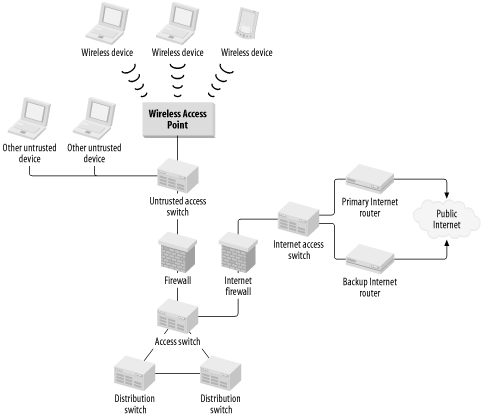
Wireless users then connect to the Access point device located behind the firewall. Once they have authenticated appropriately with the Access point, using standard 802.11 authentication systems, they establish a VPN connection through the firewall to the secure internal network. This combination of security measures gives the wireless users as much security as any standard cable-based LAN connection.
Each time I discuss firewalls in this book, I refer to IP examples. This is because, quite simply, there are no real firewalls for other protocols. It might be useful to have an IPX firewall that could handle IPX address translation and SAP proxy services, but I am aware of no such commercially available device. The reason for the large number of sophisticated IP firewalls is clearly connected to the growth of the Internet. The fact that every large organization needs an Internet connection has become a fact of life. This connection is simply not safe without a firewall, so there is extensive demand for IP firewalls. But the lack of public IPX or Appletalk networks, for example, has meant that there is very little demand for sophisticated firewalls for these protocols.
I have already mentioned that the difference between a bridge and a router is related to the OSI Layer where they operate. A bridge preserves Layer 2 information but can change Layer 1 properties. Put another way, a bridge terminates Layer 1 and continues a Layer 2 connection. A router preserves Layer 3 and changes Layer 2. It also terminates Layer 2 connections and allows Layer 3 to carry on. This distinction is important because there is considerable confusion in marketing literature about what firewalls and gateways are.
In a TCP/IP application, a router is one level of gateway device. More commonly, the word refers to an application gateway device that terminates the TCP session on one side and starts a new session on the other. It does not retain Layer 4 information like packet sequence numbers, but it does pass application data through, perhaps with reformatting. Therefore, an application gateway is a network device that operates above Layer 4.
This sort of gateway that runs the same protocol on both sides is sometimes also called a proxy host. One common application is a web proxy, which proxies HTTP connections. In this case, the proxy is done both for security reasons, allowing only one device to directly connect to the public Internet, and for efficiency. If the same web sites are visited repeatedly, the proxy host can cache the commonly viewed information. When a client device requests information from the web site that has recently been cached, it can receive it more quickly from the proxy server. This convenience has the added benefit of reducing traffic on the Internet access links.
However, some gateways also run different protocols on both sides. For example, it is relatively common to use gateways to access remote SNA services. If the workstations run a routable protocol, such as IP or IPX, they can connect to the SNA gateway device. This gateway then connects directly to the SNA host and converts the traffic in both directions.
A firewall is rarely so well defined. For instance, there are firewalls that are, in fact, little more than routers. They may do extensive packet filtering and they may even do network address translation (NAT) to change IP addresses. But their net effect is to change only Layer 3 information without necessarily terminating the Layer 4 session and establishing a new one on the other side. Some firewalls act as gateways, fully terminating each call and passing only application data through from one side to the other. Some firewalls also effectively operate as packet filtering bridges.
A firewall is a security device. It can only be defined in terms of the security it provides. An application gateway, however, is a network device with a specific network meaning. Because every firewall operates in a unique way, it is difficult to make general statements about them. Rather, it is best to evaluate specific security requirements and select a firewall that appropriately fills these requirements.
For large networks with serious security issues, I always recommend using a specially designed commercial firewall. I especially recommend it for firewalls protecting access to a public network such as the Internet. There are many ways to make a firewall, including commonly available software for the Linux operating system. These systems may work well enough for a small office or home network, but it is important to remember that network security is not simple. Building a highly secure firewall is not easy. Commercial firewall manufacturers frequently issue bug fixes and updates to correct recently discovered flaws and foil clever new attacks. It is unlikely that a homemade system will be kept up-to-date like this.
Similarly, it is not difficult to implement basic packet filtering on most commercial routers. This filtering may be sufficient for use with a semitrusted external network, such as that connecting to an external information vendor. But it is unlikely that this sort of safety measure will be adequate against a genuinely hostile environment like the Internet. If your network is valuable enough to protect with a firewall, it is valuable enough to protect with a proper firewall.
It is beyond the scope of this book to offer any particular guidance in selecting one commercial firewall over another. Essentially, all of them are good and offer excellent levels of security. However, they all have subtle differences that make some more useful in some environments than others. Furthermore, because several new security products come onto the market each year, it is best to simply evaluate security requirements at the time they arise and select the best currently available product.
However, remember that no firewall will make your network inherently secure and keep your data safe. At best, it will prevent interactive connections from the outside of your network to the inside. However, there are many ways to steal information and even more ways to corrupt information or to disrupt network services. Most of these methods do not involve interactive connections from an external network. I discuss security in more detail in Chapter 10.
One of the most important, yet least discussed, factors in building a successful LAN is a good cable plant. Of course, by cable I mean not only copper, but also fiber optic cabling. A good cable plant design considers several factors.
First, there is a difference between vertical and horizontal cable runs. In a simple high-rise office tower with one LAN room on each floor, the difference is relatively clear. Vertical cable runs interconnect the different floors, while horizontal cabling is used to connect users to the LAN Access equipment such as hubs or switches. In a more complicated real estate plan, the terms become a bit confusing because not all horizontal runs are parallel to the ground, and not all vertical cable runs are perpendicular to it.
By horizontal cable runs, I mean Access Level wiring. I only use this term to describe cables that connect end station equipment to Access hubs and switches. Vertical cabling, on the other hand, is never used for end stations. Rather, it is used to interconnect hubs and switches. In a hierarchical design, vertical cabling usually means cabling that connects Access Level hubs and switches to Distribution switches. Vertical cabling is also often used to connect Distribution to Core devices.
For the horizontal cable runs, the important considerations are:
Type of cabling employed
Number and type of connectors at each desk
Number and type of connectors in each computer room rack
Patch panel design
Physical routing of cable
The gold standard for horizontal cabling is currently Category 5 (sometimes just called Cat5). This system was originally introduced to support 10BaseT networks, with all of the required growth capability for Fast Ethernet, which was not yet commonly available. It turns out that Category 5 is even able to support Gigabit Ethernet, so the investment in a Category 5 cable plant has been well worth the money.
One of the most fortuitous features of the Category 5 specifications for Fast and Gigabit Ethernet is that, like 10BaseT, they all specify a distance limitation of 100 meters. If the cable plant was built to respect this specification, it should theoretically be able to handle these speed upgrades.
Furthermore, Category 5 cabling can also support 4 and 16Mbps Token Ring standards with the same 100-meter distance limitation. And in all cases, the same standard RJ45 connector is used, so you can freely change your environment among any of the most popular LAN standards without needing to change your cabling. This fact is important because, although the cable itself may not be terribly expensive, the cost of rewiring an entire work area to support a new cabling standard is daunting.
However, the Category 5 standard has evolved slightly since it was introduced. To support Gigabit Ethernet, it became necessary to modify the standard, called Enhanced Category 5 or Category 5e. This enhanced standard includes limits on signal reflection properties and cross talk at junctions. While it is true that a good Category 5 cable plant supports Gigabit Ethernet, if the installation is more than a few years old, it may have trouble with Gigabit speeds. The compatibility can be tested easily by any certified cabling contractor. It is definitely a good idea to pretest any cable plant before assuming that it will support an upgrade from Fast to Gigabit Ethernet.
A new Category 6 standard is currently nearing the final stages of acceptance. Some organizations have rushed to implement the new standard in the hopes that it will provide further growth capabilities. But there have been a number of reported interoperability problems with the Category 6 cable systems, mostly caused by pushing ahead before the standard was completed. Furthermore, if these organizations implement Category 6 in the hopes that it will support similar future growth to 10 Gigabit Ethernet, they may be sorely disappointed. The 10 Gigabit Ethernet project is moving ahead quickly, but has not yet settled on any copper-based cabling standard. And it is possible that they will have to bypass Category 6 and jump directly to Category 7, which is also currently in development.
The current picture of the world of cabling standards is rather uncertain. There are no guarantees that any of today's cabling standards will support tomorrow's high-speed networking. The good news is that a good Enhanced Cat5 cable plant will readily support both 100Mbps Fast Ethernet and Gigabit Ethernet speeds.
One of the best cost-saving measures available when designing a horizontal cable plant is simply deciding how many LAN drops will be put at each user work area. In general terms, the cost of pulling one cable to a desk is the same as pulling several cables. This is because the cabling contractor simply bundles all wires together and pulls the bundle. The same amount of labor is required either way. In cabling jobs, the labor cost is commonly around 75% of the total cost. Doubling the number of LAN drops at each desk will likely increase the total cost by 25%. However, coming back to pull a new bundle of cables to every desk after the original job is done can be prohibitively expensive. It is better to slightly overestimate the number of LAN drops that will be required at each desk.
An organization that expects every user to have only one network device on his or her desk should probably consider pulling two LAN drops to each desk. This way, if several users suddenly need a second workstation or a printer, it is easily accommodated with minimal expense. Similarly, if it is known from the start that a lot of users will have two network devices on their desks, then pulling at least three LAN drops would be wise.
Some organizations, particularly investment banks with large computerized trading floors, opt to pull both fiber and copper cabling to every desk. This way, they know that they will be able to support future speed increases, even if the standards for copper cabling change. But this option is probably overkill for most office applications.
Another common cost-saving measure in horizontal cabling is combining LAN and telephone cable runs, terminating them all on the same termination block at the workstation. This measure is particularly useful if the telephone system uses the same wiring closet as the LAN does.
The same considerations apply to the cabling of server racks in the computer room. Some organizations take advantage of their raised computer room floor to do all of their server cabling in an ad hoc, as needed fashion. However, this can make troubleshooting problems extremely difficult because there will be no reliable pattern associating particular racks with patch panels.
I generally recommend precabling every rack in the computer room in a rational pattern. Then, if additional cables are required, they can be pulled with minimal disruption. Remember that every time somebody works under the floor tiles, they risk disrupting power or network cables that are already present. For this reason, many organizations have strict rules prohibiting any such work during business hours. Thus, precabling the racks can result in significant time savings when connecting new systems.
Patch panels are critical to maintaining the required signal loss and reflection characteristics of LAN cabling systems. Generally, the horizontal runs that terminate under user desks are collected on patch panels in a wiring closet near the work area. The total distance limit on any twisted pair copper cable run should be kept below 100 meters because this length is the upper limit to most 802.3 and 802.5 specifications. This length restricts the service area of any given wiring closet.
The most common method for terminating the horizontal cable runs in the wiring closet is to use a patch panel of RJ45 connectors. This panel is called the station field, as shown in Figure 4-8. It was once common to also have a similar second patch panel called the equipment field that connected to LAN Access hubs or switches. However, with the advent of higher speed LAN technology, simply using the RJ45 connectors on the front of the Access equipment as the equipment field is usually preferable. You generally do not want to introduce an additional connection point, as it can result in too much signal loss and reflection.
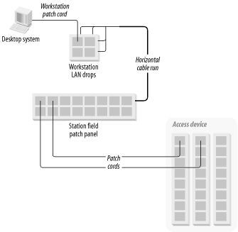
Also, to reduce signal loss and reflection, it is generally preferable to run directly from the back of the station field patch panel to the user's desk, with no intermediate terminations or patch panels. Again, in earlier implementations, using an intermediate BIX style (that is, punch-down connectors with individual wires rather than RJ45 connector jacks) panel was relatively common, since this style gave the cabling contractor extra flexibility in running the cabling.
The patch cords, both at the user's desk and connecting from the station field to the Access equipment, must be compatible with the cabling specification used for the horizontal runs and the patch panels. This compatibility becomes particularly important in Gigabit applications where signal reflections and cross talk between wire pairs can destroy the signal. In fact, existing cable plant problems are almost invariably in the patches and terminations.
One last important thing to consider when designing a cable plant is the physical routing of the cables. For horizontal cabling, this routing generally means avoiding sources of electrical noise. Fluorescent lights are some of the worst noise sources in an office building, and they are often difficult to fully avoid. However, the noise radiated from any such source decreases rapidly with distance, so an extra few feet can make a huge difference.
Usually, it is better to pull horizontal LAN cabling through the floor or walls rather than the ceiling. In an open-concept office, using walls may be impossible, however. The relatively common practice of running cables through the ceiling and down into each user cubicle by means of a hollow pole is unattractive and tends to age poorly; over time the floor layout will inevitably change. If the LAN drops come up out of a panel in the floor, it is often easy to move cubicle walls by several feet in any direction. However, with the hollow pole systems, the pole generally has to line up perfectly with the cubicle wall. Even shifting the wall by a few inches can result in a mess of bizarre angles.
Some buildings were never designed for cabling through the floor. Some building designs use thick floors of solid concrete. The only way to run cable through the floor is actually to drill through to the false ceiling of the floor below and run the cables through those holes. Drilling holes through cement (called "coring") can be extremely expensive. In these cases, it may be necessary to run the horizontal cables through the ceiling and down hollow poles, but I recommend this option as a last resort.
For vertical cabling the considerations are similar, except that you should never connect end stations directly to vertical cable runs. The important considerations are:
Type of cabling employed
Patch panel design
Physical routing of cable
The distances involved in vertical runs are often larger than the distances used in horizontal runs. This is particularly true when talking about "vertical" runs between buildings. Consequently, for vertical cabling you generally want to use fiber optic cabling instead of copper, although there are still times where copper cabling is required between floors. Vertical copper cabling, often called "house pairs," is usually run in large bundles with 25 pairs of wires twisted together, which retain the Category 5 specifications. These cable bundles are normally terminated either on an Amphenol connector or on a BIX-style punch-down block. They can be used either for standard LAN protocols over shorter distances or for legacy serial standards such as X.25 or SDLC connections.
There are two main types of fiber optic cable—single mode and multimode. Multimode fiber is less expensive, and devices that use it have lower optical power requirements, making them less expensive. However, this lower power generally means that multimode fiber is useful only for shorter distances. Most vertical cable runs use multimode fiber optic cabling. For longer distance requirements the power of the injected signal has to increase, which usually requires single mode fiber cable.
The rule has historically been that multimode fiber is used for LANs and any short distance requirements while single mode is used by WAN and MAN service providers. This rule may need to be altered because of multimode distance restrictions on Gigabit Ethernet.
The current Gigabit Ethernet specification restricts multimode fiber cable runs to 500 meters. This length is enough to reach from the top to the bottom of the world's tallest office buildings, but it is not sufficient to cross even a modest-sized campus. Thus, some organizations will probably need to pull new single-mode fiber runs between buildings to allow them to take full advantage of Gigabit Ethernet trunks.
Fiber patch panels are similar in concept to patch panels for twisted pair cabling. Usually, a bundle of fibers is run from any given LAN wiring closet to a central Distribution LAN room. Multimode fiber comes in a variety of different bundles. The smallest bundles generally include only a single pair of fibers. As with horizontal LAN cabling, the main expense in pulling a bundle of fiber optic cable is in the labor, not the cable. Thus, it is usually wise to pull a larger bundle of fibers, even if there is no immediate requirement for more than one pair. Remember that fiber is almost always used in pairs, so it is easy to use up all available strands quickly when new requirements emerge.
The usual method for running vertical fiber cabling is to designate a few Distribution LAN rooms where the Distribution Level switches will be housed. Then all Access devices that use this Distribution Area will be housed in local wiring closets. You need to run at least one bundle of fibers from each local wiring close to the Distribution LAN room. Then you can simply use fiber patch cords to connect the Access equipment to the patch panel on one end and the Distribution equipment to the patch panel on the other end.
Fiber optic cabling is not susceptible to electrical interference. It is, however, far more susceptible to cutting and breaking than copper wire. You can use two common methods to help protect against these problems.
First, though the fiber bundles themselves are held together in a protective sheath, this sheath is not sufficient to protect the delicate fiber from damage. The bundles are usually passed through long metal conduits, which helps protect them against damage from accidental bumping or crushing.
Second, and most important to a stable LAN design, running two sets of fiber bundles through different conduits is a good idea. It is even better if these conduits follow completely different physical paths. For example, in many cases, vertical cabling runs through the elevator shafts of a building. The preference here would be to run two bundles through separate conduits located in different elevator shafts. This way, even if a fire or other similar disaster in the building destroys one physical path, it doesn't destroy your only way of connecting to a remote area.
In this case, you would also carefully construct your trunks so that you always run redundant pairs of trunks, one from each conduit. Then if you have a physical problem that damages one fiber bundle, Spanning Tree or some other mechanism will activate the backup trunk and there will be no service outage.
Another good reason to use physically separate fiber conduits is that fiber cable itself is susceptible to low levels of background radiation. If one conduit happens to pass through an area that has unusually high radiation (a radiology office, or perhaps some impurity in the concrete), then over time the fiber could become cloudy and start showing transmission errors. In this case, the other conduit will probably not have the same problem. Thus, you can simply switch over to the backup link.
[1] It is customary to use the word "frame" when talking about the Layer 2 view of a chunk of data and the "packet" at Layer 3.
[2] Note that this length is the size of the packet's data segment. If you include the MAC header's 6-byte source and destination addresses, the length/type field itself, and the 4-byte checksum at the end of the packet, the maximum Ethernet frame length is 1518 bytes. The 8-byte Ethernet preamble is not included when people talk about frame sizes.
[3] See the paper "Intercepting Mobile Communications: The Insecurity of 802.11" by Borisov, Goldberg, and Wagner, published in the proceedings of the Seventh Annual International Conference on Mobile Computing and Networking, July 16-21, 2001.
Get Designing Large Scale Lans now with the O’Reilly learning platform.
O’Reilly members experience books, live events, courses curated by job role, and more from O’Reilly and nearly 200 top publishers.

