Dynamic Host Configuration Protocol (DHCP) is an Internet standard protocol designed to dynamically allocate and distribute IP addresses as well as additional TCP/IP configuration information. DHCP is defined by RFCs 2131 and 2132. Working with the Internet Engineering Task Force (IETF) and a number of other vendors, Microsoft was instrumental in the development and standardization of DHCP.
Before the advent of DHCP, most TCP/IP configurations were maintained statically. An administrator configured each individual host with a valid IP address, subnet mask, and default gateway, as well as other TCP/IP configuration parameters. As you can guess, configuring and administrating static TCP/IP configurations for multiple workstations and network devices can be a burdensome task, especially if the network is large and/or changes frequently. The exception to the rule was the use of two predecessors to DHCP, the RARP and BOOTP protocols. These protocols are covered in more detail in Chapter 2.
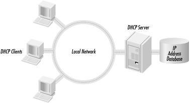
DHCP uses a client/server model of operation (see Figure 1.1), where a DHCP client makes a request to a DHCP server for an IP address and other configuration parameters. When the DHCP client makes the request, the DHCP server assigns it an IP address and updates its database, noting which client has the address and the amount of time that the address can be used. This amount of time is known as a lease. When the time expires, the DHCP client needs to renew the lease or negotiate a new lease for a different IP address. Through the use of leases, the DHCP server can reclaim unused IP addresses.
Using DHCP allows an administrator to make changes to a client’s IP configuration without the need to visit each and every client. The user at the workstation only needs to release and renew their DHCP lease. That is the power and benefit of DHCP.
The purpose of this chapter is to provide an overview of the data that DHCP is expected to deliver: TCP/IP configuration information. The TCP/IP protocol suite is the common language of the Internet and by far the dominant networking protocol suite in use today. One must understand the many different facets of the TCP/IP protocol suite in order to configure, maintain, and troubleshoot a Windows 2000 DHCP server.
This chapter begins with an overview of the TCP/IP protocol suite, describing the different functions at the different layers of the Open Systems Interconnection (OSI) Model. It then covers Media Access Control (MAC) addresses—what they are and how they operate, followed by a very important area that one must understand: IP addressing and subnetting. The next two sections finish up the chapter by giving an overview of the two types of name resolution used in Microsoft Networking: DNS and WINS.
In the 1960s, the Department of Defense’s Defense Advanced Research Projects Agency (DARPA) was in charge of developing a means of communication that would still function in the event of a nuclear war. Development focused on the new theory of the packet-switched network. All forms of networking up to this time (i.e., the phone system) had used a circuit-switched network.
A circuit-switched network connects the sending and receiving stations by a single, direct physical path. Circuit-switched connections are not shared with other traffic; they are meant to be one-to-one. The telephone system is an example of a circuit-switched network. When a person dials a phone number, the phone company equipment establishes a direct connection between the caller’s phone and the receiving phone. This connection lasts for the duration of the call.
A packet-switched network operates by breaking the data to be transmitted into smaller datagrams or packets. Each of these packets is numbered and sent out across the network. Because the packets are individually numbered, they can take multiple paths to their destination. There they will be put back in order and reassembled into the original data.
Figure 1.2 illustrates the concepts of these two types of networks.
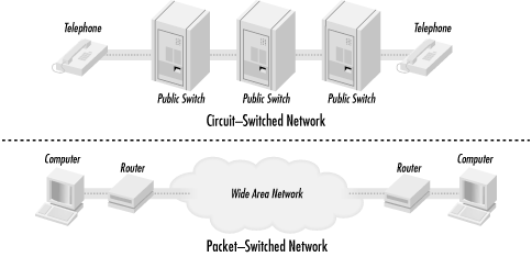
The weakness with a circuit-switched network is that communication links have to be set up ahead of time. If a circuit goes down, communication stops. The beauty of a packet-switched network is that if a point of communication goes down, the data is automatically rerouted through another location dynamically. In the end, it had great battlefield potential—which is what DARPA was looking for. If a command center was taken out, communications could continue by rerouting the data across any available medium: packet radio, satellite links, land links, etc.
The TCP/IP protocol suite was developed and refined as part of the packet-switched network project.
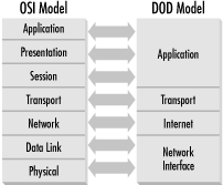
The TCP/IP protocol suite can be used to communicate over any type of networking medium. This includes Local Area Network (LAN) and Wide Area Network (WAN) environments. TCP/IP accomplishes this by using a modular design. The blueprint of this modular design comes from the Department of Defense (DOD) Reference Model. The International Standard Organization (ISO) also developed a seven-layer reference model called the Open Systems Interconnection (OSI) Model. These models provide networking hardware and software vendors with guidelines to create products that will be compatible in form and function across multiple hardware and operating system platforms.
The DOD Reference Model consists of only four layers that are closely aligned with the OSI Reference Model (see Figure 1.3):
- Application Layer
This layer provides application interfaces, session establishment, data formatting, and data conversion for applications running on a host system. This layer coincides with the upper three layers of the OSI Model: Application Layer, Presentation Layer, and Session Layer.
- Transport Layer
This layer defines the method of communication between two systems: connection-oriented or connectionless. This layer maps directly to the Transport Layer in the OSI Model.
- Internet Layer
The Internet Layer defines internetworking communications (i.e., routing). This layer maps directly to the Network Layer of the OSI Model.
- Network Interface Layer
This layer defines data-link and media access methods (i.e., Ethernet, Token Ring, FDDI). This layer includes the remaining two layers of the OSI Model: Data Link and Physical Layers.
The Application Layer defines protocols that provide email, file transfer, remote logins, and drive-mapping capabilities to user applications. Some examples of protocols from the TCP/IP Protocol Suite that reside at this layer are Telnet, FTP (File Transfer Protocol), SNMP (Simple Network Management Protocol), SMTP (Simple Mail Transport Protocol), and DNS (Domain Naming System).
The Transport Layer defines two protocols: Transmission Control Protocol (TCP) and User Datagram Protocol (UDP). These protocols provide two separate functions:
- Transmission Control Protocol (TCP)
TCP is a connection-oriented protocol. This means that TCP will provide a reliable connection between two systems. TCP accomplishes this by sending acknowledgments periodically to determine that datagrams are being received. If the datagrams were not received, TCP resends them, thus insuring reliable delivery. TCP is also responsible for breaking the data down into individual segments, numbering them, and reassembling them at the destination.
- User Datagram Protocol (UDP)
UDP is a connectionless protocol. Unlike TCP, UDP does not use any acknowledgments, sending data blindly out onto the network to the destination. UDP assumes that another layer, usually provided by timers and timeout periods, will handle error correction. Implementations such as these are integrated into applications by the developer. Since UDP does not have the overhead of TCP, it is considered quick and efficient.
The Internet Layer is responsible for the delivery of packets across an internetwork. There are two protocols that operate at this layer, Internet Protocol (IP) and Internet Control Message Protocol (ICMP).
IP is the engine of TCP/IP, in charge of routing packets to and from logical addresses (i.e., IP addresses). These logical addresses correspond to particular systems located on the network.
IP addresses are organized in a hierarchical manner, allowing networks to be subdivided into subnets.
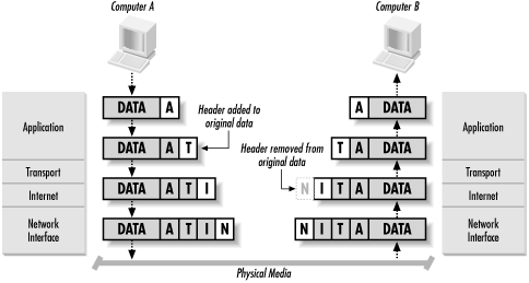
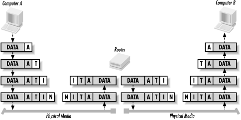
When a system wants to transmit data to a destination on a local network, IP takes the data segment provided by TCP. It then adds a header to the segment that includes the destination IP address and determines the destination’s local subnet. IP sends the resulting packet to the source’s network interface, and thus to the local network. At the destination, IP receives the packet, strips off the header information, and sends the resulting segment up to TCP. TCP reassembles the data and sends it to the appropriate application (see Figure 1.4).
If the destination is not located on the same local network as the source, IP performs additional steps to transmit the data.
IP first takes the data segment provided by TCP. It creates and attaches the header to the data segment and determines whether the destination is on a local or remote subnet. In this case, since the source and destination are not on the same local network, IP sends the packet to the default gateway (i.e., the router on the local subnet).
At the router, IP receives the packet and, after analyzing the destination IP address, determines that the packet is destined for another host on a remote subnet. IP determines the subnet address for the destination and routes the packet to the network interface attached or closer to the destination’s local subnet.
Finally, the destination receives the packet, strips off the header, and sends the data segment to TCP for reassembly (see Figure 1.5).
I will discuss IP addresses and subnetting in more detail later in this chapter.
ICMP provides message packets that report errors and other information, such as network congestion, that may be affecting IP packets. There are some situations when this may occur:
The destination may be unreachable because there is no route.
The host may be unreachable because of a configuration issue or because a gateway does not have the buffering capacity to forward the packet.
ICMP can also notify the source host that a more efficient route exists.
ICMP also provides an echo-request message. These messages are
created by the ping command and are used to test
connectivity between hosts on an internetwork. The
tracert command also uses this mechanism to
determine the router list and report the time between routers (known
as hop time).
Finally, if an IP packet’s Time to Live (TTL) field has reached zero, a router discards the packet. The router then generates an ICMP time-exceeded message to notify the source host that the packet was discarded.
The Network Interface Layer provides data link and media access capabilities to the upper-level layers via hardware addresses. This layer allows TCP/IP to function across multiple media-access protocols, such as Ethernet, Token Ring, FDDI, Frame Relay, ISDN, and xDSL.
- Ethernet
Invented by Xerox, Ethernet is a baseband LAN specification that uses Carrier Sense Media Access/Collision Detection (CSMA/CD). Ethernet can operate at 10 Mbps over various cable types. There are also newer and faster implementations of Ethernet available.
- Token Ring
Invented by IBM, Token Ring is a token-passing LAN specification. Computers in a Token Ring environment are connected to the network media in a closed ring. Whichever computer possesses the Token is permitted to transmit data on the ring. When the computer is finished transmitting, it passes the token on to the next computer in the ring. If the next computer does not need to transmit, it, too, passes the token on. By employing a token-passing scheme, collisions are avoided, since only one computer is permitted to transmit. Token Ring can operate at 4 or 16 Mbps.
- Fiber Distributed Data Interface (FDDI)
FDDI is a 100 Mbps, token-passing LAN standard using fiber-optic cables. FDDI uses a token-passing scheme similar to Token Ring. FDDI consists of two fiber-optic rings, a primary ring and a backup ring in case the primary fails. FDDI using multimode fiber can operate up to a distance of 2 km. FDDI using single mode fiber can operate to a distance of 40 km.
- Frame Relay
Frame Relay is a telecommunications service meant to be used as a WAN technology. It is the medium by which multiple LANs can be linked together. Frame Relay operates by placing data into a frame for transmission. A virtual circuit connection is created between two end devices, over which the frame is sent. Frame Relay provides no error correction, so the devices on either end of the connection must supply error correction. A switched data link layer protocol, Frame Relay can handle multiple virtual circuits.
- Integrated Services Digital Network (ISDN)
A digital communication protocol, ISDN can carry voice and data through conventional copper telephone networks. An ISDN line is comprised of two different channels, B and D. B (or bearer) channels are the main conduits for data and voice communications. D (or data) channels are used to transmit setup and control signals for the entire ISDN connection. ISDN comes in two levels of service: Basic Rate Interface (BRI) and Primary Rate Interface (PRI). BRI consists of two B channels (64 Kbps) and one D channel (16 Kbps). As a result, BRI ISDN operates at speeds up to 128 Kbps. PRI consists of 23 B channels and one 64 Kbps D channel. PRI ISDN operates at up to 1.544 Mbps. An ISDN adapter must be installed on both ends of the connection to handle the digital signal.
- xDSL
A digital technology that uses the existing copper telephone infrastructure to transmit voice and data. Typical telephone wire in the United States contains four wires. Only two of the wires are used for telephone service; the other two remain unused. xDSL utilizes all of the wires to carry a digital signal at a frequency higher than that of voice communications. As a result, a telephone line utilizing xDSL can carry voice and data communications simultaneously. xDSL is a faster alternative to ISDN and operates at a number of speeds such as 640 Kbps, 1.6 Mbps and up. Currently xDSL suffers from major distance limitations, usually less than 20,000 feet from the central telephone office.
I briefly describe Ethernet here because it is by far the most popular LAN technology. It is cheap, easy to use and understand, and flexible.
Ethernet uses a media access process known as CSMA/CD (Carrier Sense Media Access/Collision Detect). This works by allowing any host on the network to transmit at any time, but before transmitting, the host must listen for traffic on the network. If no traffic is detected, the host can proceed. If two hosts on the network transmit at the same time, a collision occurs. When a collision occurs, the offending stations are each set to wait a random length of time before retrying the transmission.
Ethernet comes in primarily three flavors: IEEE 802.3 (10 Mbps), Fast Ethernet (100 Mbps), and Gigabit Ethernet (1000 Mbps).
- IEEE 802.3
The standardized version of Ethernet. It operates at a data rate of 10 Mbps.
- Fast Ethernet
A form of Ethernet that provides a data rate of 100 Mbps. Workstations that are equipped with IEEE 802.3 network adapters can connect to a Fast Ethernet-based network, however they are still limited to 10Mbps data transmission.
- Gigabit Ethernet
Another form of Ethernet that provides a data rate of 1 Gbps, or 1 gigabit. Gigabit achieves its tremendous speed by using fiber-optic cable as the network medium. Copper cabling can also be used, but it severely limits the distance Gigabit Ethernet can operate at. Workstations equipped with IEEE 802.3 and Fast Ethernet network adapters can attach to Gigabit Ethernet, but they are still limited to their respective data transmission rates.
This essentially concludes the discussion of the DOD Reference Model. The remaining sections of this chapter deal with more specific TCP/IP concepts. This provides an understanding of some of the configuration parameters that a DHCP server provides to DHCP clients.
Get DHCP for Windows 2000 now with the O’Reilly learning platform.
O’Reilly members experience books, live events, courses curated by job role, and more from O’Reilly and nearly 200 top publishers.

