IP addressing is the heart of the TCP/IP-based internetwork. The process of routing IP packets is possible because of this logical addressing scheme.
An IP address is a logical 32-bit binary number that identifies a system on an internetwork. An IP address comprises two parts—the network portion and the host portion. The network portion of an IP address tells the host what logical network it is located on. The host portion identifies that particular host.
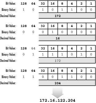
Because humans tend to have trouble remembering and evaluating binary numbers, IP addresses are expressed in dotted decimal notation. A 32-bit binary IP address is written out in four octets, each of which contains eight bits. Each bit position in an octet represents a value (one of 128, 64, 32, 16, 8, 4, 2, 1); the sum of these values, when totaled, represents the octet’s decimal value (see Figure 1.9).
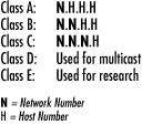
Initially, when IP was developed, the IP address space was divided into distinct IP address classes to determine where the network portion stops and the host portion begins. The value of the first octet and its highest order (leftmost) bits determine the class. There are five IP address classes, three of which (A, B, and C) are available for commercial use (see Figure 1.10). Class D is reserved for IP multicasting. Multicasting allows multiple computers in the same multicast group to receive the same data transmission, sort of like a directed broadcast. Class E is strictly reserved for research use by the Internet Engineering Task Force (IETF).
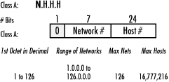
In a Class A IP address, the network portion is represented by the first octet; it has 0 in its leftmost bit. In other words, if you were to set all the remaining bits in the first octet to 0s, the resulting value for the octet would be 0. If you set all the remaining bits in the first octet to 1s, the resulting value would be 127. Therefore all Class A IP addresses fall into the 0-127 range for the first octet. This also results in 127 possible networks and a maximum of 16,777,214 hosts on each network. (Please note that the network 127.0.0.0 is reserved for loopback addresses.) Figure 1.11 summarizes the characteristics of the Class A address class.
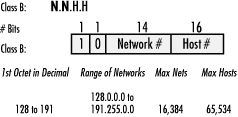
In a Class B IP address, the first and second octets represent the network portion; it has 10 in its two leftmost bits. A Class B IP address falls into the 128 to 191 range for the first octet. This results in 16,384 possible networks and a maximum of 65,534 hosts on each network. Figure 1.12 summarizes the characteristics of the Class B address class.
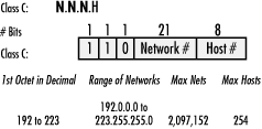
In a Class C IP address, the network portion is represented by the first, second, and third octets; it has 110 in its three leftmost bits. A Class C IP address falls into the 192 to 223 range for the first octet. This results in 2,097,152 possible networks and a maximum of 255 hosts on each network. Figure 1.13 summarizes the characteristics of the Class C address class.
Please note that some host and network addresses cannot be used. These are discussed later in this chapter.
IP address classes are not always the most efficient way to design an IP addressing scheme. There aren’t many companies that need a Class A address with 16 million hosts, and there may be smaller companies that need more addresses than a Class C network can provide. As you can see, this method could lead to a tremendous number of wasted IP addresses. The Internet Engineering Task Force (IETF) saw this and submitted RFC 950 to facilitate the addition of a third level to the existing two-level hierarchy created with IP address classes.
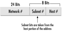
This third level is known as subnetting. Subnets are created by taking leftmost bits from the host portion of an IP address and applying them to the network portion (see Figure 1.14).
Subnetting gives network designers and administrators the ability to divide larger networks into smaller, more efficient networks. Since subnets are under local administration, the outside world (via routing tables) does not need to know of their existence.
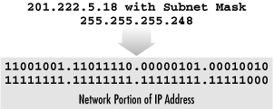
Subnetting is made possible by the use of a subnet mask. A subnet mask, along with the IP address classes, determines where the network and subnet portions of an IP address end and the host portion begins. A subnet mask is a 32-bit binary number. Starting at the leftmost bit, 1s are placed in every bit that is part of the network and subnet portions. The remaining bits contain 0s (see Figure 1.15).
So how does IP determine the subnet where a host is located? There is a set process that a router or host performs to determine the subnet address. This process is commonly known as Logical ANDing. Logical ANDing is simply a Boolean operation that follows three basic rules: 1 “ANDed” with 1 is 1; 1 “ANDed” with 0 is 0; 0 “ANDed” with 0 is 0. In other words, if 1 = True and 0 = False:
|
1 “ANDed” with 1 is 1 |
True AND True = True |
|
1 “ANDed” with 0 is 0 |
True AND False = False |
|
0 “ANDed” with 0 is 0 |
False AND False = False |
The process begins with the IP destination address and the internal subnet mask. A Logical AND operation is performed which causes the host portion of the destination IP address to be removed—resulting in the subnet address. Here’s an example where the ANDing operation is performed on a Class C subnet. Take a moment and observe the last octet in the IP address:
|
Destination IP Address: |
|
|
|
Subnet Mask: |
|
|
|
Resulting Subnet Address: |
|
|
Given the preceding example, we have determined that the IP address 192.168.0.214 with a subnet mask of 255.255.255.224 is located on the subnet 192.168.0.192.
Taking the example further, what is the maximum number of hosts on this segment and what are the starting and ending IP addresses?
Before we answer these questions, I want to introduce you to a little formula that makes life in the IP world easier. This formula is 2n -2. Using this formula, one can determine the number of hosts in a subnet. 2n represents the number of hosts that can be created, where 2 is the number of possible values for each bit (0 or 1—remember we’re dealing in binary here!) and n is the number of bits taken from the host portion of the network address. I subtract two from 2n because addresses of all 1s and all 0s cannot be used.
Now let’s take a moment to answer the first question: what is the maximum number of hosts on this subnet, 192.168.0.192? This can be determined by examining the portion of the subnet mask that is not masked, or contains 0’s. For the subnet mask of 255.255.255.224, the host portion contains 5 zeros. This means that the n exponent in our trusty little formula would have a value of 5. The number of hosts is then 25-2. Which results in...get out those calculators...30. So, on subnet 192.168.0.192, the maximum number of hosts is 30. That wasn’t so bad, was it?
OK, we answered the first question. Now let’s figure out the second question: what are the starting and ending IP addresses on subnet 192.168.0.192? Or another way to ask this question is, what is the range of IP addresses on subnet 192.168.0.192?
To answer this we need to again examine the subnet mask 255.255.255.224.
First, note that we are only concerned with the last octet, 224, since this octet contains the host addresses. Take 224 and convert it into binary. This results in 11100000. To figure out the address ranges possible with this subnet mask, we need to determine the value of the furthest bit to the right that is set to 1. For this subnet mask, there are three 1s, and the last set bit is 32.
This value, 32, is known as the subnet offset value. The subnet offset value tells you that every 32 addresses results in another subnet. We can now determine the subnet’s address range by taking the subnet address, 192.168.0.192, and adding 32, which results in 192.168.0.224. 192.168.0.224 is the start of the next subnet after 192.168.0.192.
Since 192.168.0.224 is the start of the next subnet, let’s subtract 1 from this address, which results in 192.168.0.223. This is the last host address in the 192.168.0.192 subnet. Determining the first host address is simple: add 1 to the subnet address, 192.168.0.192, which results in 192.168.0.193.
So, to answer the second question, 192.168.0.193 is the first host address, and 192.168.0.223 is the last host address in the 192.168.0.192 subnet.
Note that if we set another bit to 1 in the subnet mask, or, in other words, move the masked bits further to the right, the subnet offset value gets smaller. This results in a smaller address range, or fewer hosts per subnet. If we move the masked bits to the left, the subnet offset value grows larger, resulting in larger address ranges.
Now let’s expand our discussion to the enterprise level. Here we will walk through a situation where subnetting would be used in a large internetwork environment. An organization has been assigned the Class C network address 201.222.5.0. This company has 20 remote offices, each containing 5 workstations and a server.
First, determine the subnet field size that will yield enough subnets in this situation. Remember the 2n -2 formula? Using that formula again, one can determine the number of subnets created.
In our example, the network address is 201.222.5.0. We know that it is a Class C address because the first octet falls into the Class C range: 192 to 223. Given that it is a Class C address, the network portion is made up of the first three octets. This represents 24 bits from the 32 bits in the address. This leaves the remaining octet, or 8 bits, for the host portion. Now let’s determine the number of bits required. Using the formula 2n -2, simply plug in the number of bits. 25-2 = 30 possible subnets, which provides the required 20 subnets, with 10 left over for future growth.
Why use 5 bits? Why not use 4? 24-2 = 14 subnets, which is not enough. Using 6 bits, 26-2 = 62 subnets, which works for the subnets but does not leave enough host addresses.
Recall that the bit furthest to the right is the subnet offset value. This value determines the subnet addresses.
We used 5 bits for the subnet portion. The fifth bit value from the right is 8. Therefore the subnet addresses are all multiples of 8: the first subnet is 201.222.5.8, the next is 201.222.5.16, etc.
The host address range begins with the subnet address plus 1. The range ends with the next subnet address minus 2.
Our first subnet is 201.222.5.8. The host range for this subnet would be 201.222.5.17 through 201.222.5.22.
To conclude, IP subnetting happens to be one of those subjects that many people do not immediately comprehend. It needs to be studied and put to practical use. Once this happens, people understand it, and they never forget it. Give subnetting time and work with it. It will “click.”
As the Internet unexpectedly grew in popularity, it became apparent that something must be done about the depletion of registered Internet networks and the growth of Internet routing tables. In particular, Class B networks were nearly completely allocated by the late 1980s. The reason for the depletion of this particular class was the lack of a class whose size was appropriate for a mid-size organization. A mid-size organization would require more than the maximum 254 hosts a Class C network provides, while the 65,534 hosts a Class B network provides were too many. If an organization needed more than 254 hosts, it would be assigned a Class B network, essentially wasting many IP addresses.
Classless Interdomain Routing (CIDR), defined in RFC1519, was implemented to slow the growth of the Internet routing tables and the need to allocate more network numbers.
CIDR slows routing table growth by aggregating multiple networks to form a single network. This is known as supernetting. Supernetting also alleviates the Class B address depletion problem by allowing multiple Class C networks to be aggregated. These aggregrated Class C networks provide a number of hosts somewhere between a Class C and a Class B network.
For example, a company requires 6500 host addresses. To achieve this without allocating a Class B address, the company is issued the network address 192.168.0.0/19. The /19 represents the number of bits in the network number, much like a subnet mask. This network actually represents 32 Class C addresses, 192.168.0.0 to 192.168.31.0. The IP address utilization level of the 192.168.0.0/19 network is almost 80%, whereas the utilization level of a Class B network would have been about 10%. Also, only one route is added to the routing table. When a router outside the company needs to send data to a host on subnet 192.168.16.0, it uses the 192.168.0.0/19 routing table entry. The company’s router then forwards the data to the correct subnet.
CIDR solves the two problems of growing router tables and the need for more network addresses quite nicely; however, there is an issue that needs to be considered. If you are working entirely with modern routing technology, such as the routing protocol Open Shortest Path First (OSPF), using CIDR is possible and not entirely difficult. However, if you are using older technology such as Routing Information Protocol v.1 (RIP1), CIDR cannot be used. RIP1 uses IP address classes to determine routes to a network. It does not use subnet masks to determine the network address. It simply observes the address’ first octet to determine which class the IP address belongs to. So keep this in mind if you want to use CIDR.
Certain IP addresses have special meanings and therefore cannot be used. Table 1.2 lists these addresses and describes why they cannot be used. Please note that some newer networking equipment allows some use of these restricted addresses. Refer to your equipment’s operating manual for more information.
Table 1-2. Special IP Addresses and Their Uses
Get DHCP for Windows 2000 now with the O’Reilly learning platform.
O’Reilly members experience books, live events, courses curated by job role, and more from O’Reilly and nearly 200 top publishers.

