2.13 The Ground and Power Planes as a Tapered Transmission Line
A ground and power plane can be viewed as a parallel plate capacitor where a via and a trace is used to make a connection to one of the planes. When a connection is made in the middle of a board, the conductor geometry can be viewed as a tapered transmission line (TTL). In this geometry, the characteristic impedance varies with the radial distance from the point of entry. Energy is moved by waves that move radially into or out of the points of contact. When a switch connects a resistive load to the point of entry, the initial wave travels outward radially.
To understand how energy is transported, we will first consider the characteristic impedance of a thin annular ring at a distance r from the point of entry. This geometry is shown in Figure 2.10.
Figure 2.10 (a) A thin annular ring of a tapered transmission line. The H field is circular, the E field goes between the conducting planes, and the current I flows radially in the conducting planes. (b) The ![]() field pattern in the annulus.
field pattern in the annulus.
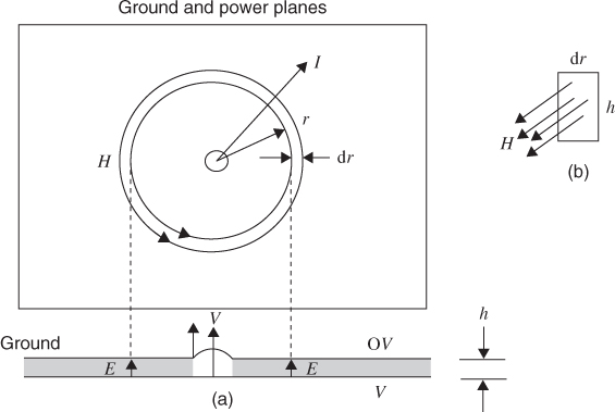
The capacitance between two circles of radius r and r + dr and of thickness h is simply
2.13 ![]()
where A is the area, h is the spacing between ...
Get Digital Circuit Boards: Mach 1 GHz now with the O’Reilly learning platform.
O’Reilly members experience books, live events, courses curated by job role, and more from O’Reilly and nearly 200 top publishers.

