2.17 Series (Source) Terminating a Transmission Line
It is good practice in fast digital logic to use a series line matching resistor at the logic source. This circuit is shown in Figure 2.14.
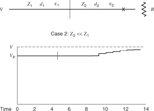
Figure 2.14 Voltage at the load for Case 2 where Z2 Z1.
When the logic transitions to a voltage V, the voltage that propagates down the line is V/2. When this wave reaches the open end of the line the reflected wave is equal to V/2. The reflected wave cancels the current and raises the voltage to V along the length of the line. When the reflected wave reaches the source, the voltage is V at both ends of the line and the current is zero. At this time, all wave action stops and no further energy is supplied to the line.
There are several benefits to this approach. The current supplied by the logic is one-half the value for the end (parallel) termination case. Radiation levels are lower, because the wave voltage is half the driving voltage. The energy supplied to the transmission line equals the energy stored in its capacitance plus the energy dissipated in the matching resistor during the round trip time. Several lines may be driven in parallel when each line is supplied with a line matching resistor.
Get Digital Circuit Boards: Mach 1 GHz now with the O’Reilly learning platform.
O’Reilly members experience books, live events, courses curated by job role, and more from O’Reilly and nearly 200 top publishers.

