2.19 Stubs
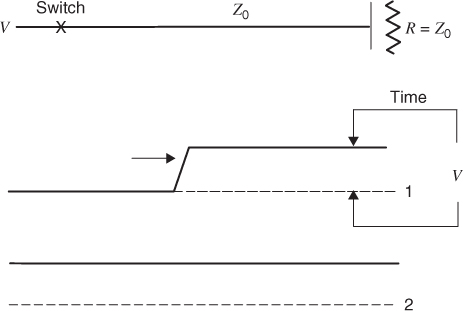
A stub is a short section of transmission line, which is parallel connected to a longer or main transmission line. This configuration is shown in Figure 2.16.
Figure 2.16 A parallel terminated transmission line.

The stub allows a logic signal to be parallel connected to two different points in the circuit. In general, stubs are not terminated in a matching impedance. Stubs will often terminate at a gate on an IC. The termination will usually be slightly capacitive, but in our analysis, we will consider it as an open circuit.
At a clock rate of 1 GHz, the rise time must be less than 100 ps. The distance a wave travels in 100 ps is 1.5 cm. One-quarter of this distance is 0.375 cm. This means that in any realizable gigahertz circuitry, stubs should be avoided.
In Figure 2.17 that follows, the logic level is a nominal 1.0 V. In practical applications, this voltage must be scaled for the logic that is used. High speed logic voltage can be as low as 800 mV or as high as 3.5 V.
Figure 2.17 A stub added to a transmission line.
Figure 2.18 The signals on a serial terminated transmission line with a stub at its midpoint.
Get Digital Circuit Boards: Mach 1 GHz now with the O’Reilly learning platform.
O’Reilly members experience books, live events, courses curated by job role, and more from O’Reilly and nearly 200 top publishers.

