2.7 The Open Circuited Transmission Line
Consider the open circuit transmission line in Figure 2.5a. The diagram is a one-line representation of a two conductor circuit as shown in Figure 2.4. When the switch closes, a step wave (1) of voltage V progresses down the line. When wave (1) reaches the end of the open-ended transmission line, a reflected wave (2) must cancel the current at the end of the line. Poynting's vector for wave (2) requires that only the H field in this wave must reverse in direction. As wave (2) progresses back on the line, the currents sum to zero. The voltage of wave (2) has the same polarity and voltage as the initial wave. Wave (2) simply adds to the voltage placed on the line by wave (1). The result is that the voltage on the line doubles, as wave (2) returns to the voltage source. It is important to note that energy is flowing from the source from the time the switch closes until wave (2) returns to the source.
Figure 2.5 (a) The sequence of individual waves generated on an open line after a switch closure and (b) the wave forms at points A and B.
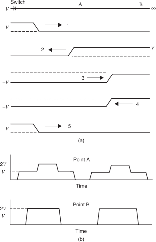
When wave (2) reaches the source, the voltage is incorrect. The reflection of wave (2) is wave (3) that moves forward on the line. It is a negative voltage − V. The sum of waves (1), (2), and (3) is simply V. The current for wave (3) is supplied by wave (2). This means that zero current is supplied by the source ...
Get Digital Circuit Boards: Mach 1 GHz now with the O’Reilly learning platform.
O’Reilly members experience books, live events, courses curated by job role, and more from O’Reilly and nearly 200 top publishers.

