5.2 The Envelope of Permitted Logic Levels
Every logic type has a set of specifications that defines the voltage range for a logic 1 and a logic 0. This permitted range of operation includes temperature variations and parameter differences in manufacturing. If a logic level is outside of this specified range, the manufacturer does not guarantee performance. If a logic 1 is too low or a logic 0 is too high, the logic transition at clock time is undefined. If the logic 1 is too high or the logic 0 is too low, there can be a logic error or damage to the product. As an example, the envelope of permitted values for TTL logic is shown in Figure 5.1. TTL is used as an example even though this logic class is not in common use. Newer logic types will have different rise and fall times, as well as different operating voltages. The TTL logic shows the 0.7-V clamping levels when silicon diodes are used. Not all logic provides clamping diodes. In some high speed logic, Shottkey diodes are used where the clamping voltage is 0.3 V. Regardless of the logic class, the arriving voltage (logic) must lie between the two outer curves or the circuit may not function properly.
Figure 5.1 The envelope of permitted logic levels for TTL logic.
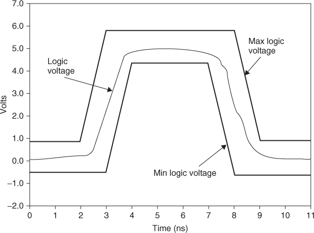
In this example, the nominal logic levels are 0 and 5 V. The upper limit for TTL is 5 V plus the breakdown voltage of the internal diode clamp or 5.7 V. The lower ...
Get Digital Circuit Boards: Mach 1 GHz now with the O’Reilly learning platform.
O’Reilly members experience books, live events, courses curated by job role, and more from O’Reilly and nearly 200 top publishers.

