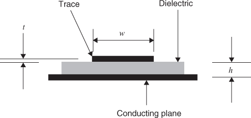
6.3 Microstrip
Microstrip refers to the traces on the outer layers of a circuit board. Some drawings show a trace resting on top of the dielectric of a given thickness. Others show the trace as partially embedded in the dielectric. The characteristic impedance Z0 for the microstrip, as shown in Figure 6.1, is given in Equation 6.1:
This equation will give good results for 0.1 < w/h < 3 and where ε R < 15.
Figure 6.1 Microstrip geometry.
It is interesting to hold the characteristic impedance constant and note the relationship between trace width and dielectric height. Figures 6.2–6.4 show curves of constant characteristic impedance, where the dielectric constant is 4. If the dielectric constant is 3.5, the characteristic impedance rises 5%.
Figure 6.2 Microstrip. Trace width versus the dielectric height needed to hold the Z0 constant. Trace thickness equals 1.5 mil.
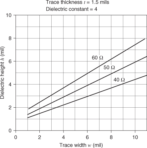
Figure 6.3 Microstrip. Trace width versus the dielectric height needed to hold the Z0 constant. Trace thickness equals 2.0 mil.
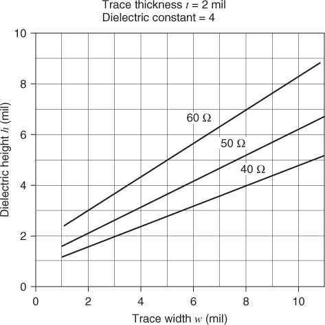
Figure 6.4 Microstrip. Trace width versus the dielectric height needed to hold the ...
Get Digital Circuit Boards: Mach 1 GHz now with the O’Reilly learning platform.
O’Reilly members experience books, live events, courses curated by job role, and more from O’Reilly and nearly 200 top publishers.

