For those who are interested in a more thorough analysis of how the solar cells charge over an orbit, we can go into depth using the aforementioned Wes Faler analysis. His simulation and calculation, running in full about five pages, is an excellent breakdown of the issues involved. His own note on it mentions “the calculations have been updated to use the AM0 space spectrum with a power density of 1366.1 W/m2 rather than AM1.5 spectrum (1000 W/m2) quoted on the solar cells for ground operation.” I’m presenting a summary of his analysis here, both to provide specific information on TubeSats and, more generally, to show how to analyze and simulate orbital conditions for a project.
Let’s break down his work into pieces. First, he sets up the physical units for the solar cells and for the orbit:
- photoWidth = width of photocell panel (meters) = 0.02109
- photoRadius = distance from center to face of photocell panel (meters) = 0.04343
- photoAngle = angle of circle for one photocell panel (radians) = 27.295 × 2π/360
- alAngle = angle of circle for one aluminum strip, radians) = 17.632 × 2π/360
- photoLength = length of the photocell panel, meters = 0.127
- wattPerPanel = 2.277 cm2/cell × 0.27 efficiency × 0.1366 W/cm2 × 6 cells/panel = 0.4928
- halfOrbitSeconds = seconds for half of an orbit at 310 km = 45 × 60
Of particular interest is that the watts per panel comes out to just under half a watt for an ideal cell (of normal efficiency). The problem to solve is whether, in orbit, we can actually achieve this. Remember we start with his conclusion—a six-cell panel can produce a half watt. So this suggests we operate at about one-sixth efficiency because of orbital issues.
What Wes considers is, first, the panel positioning. After setting up the geometry, he rotates the panels around the TubeSat center and determines, relative to the line to the Sun (placed along the +X axis), which panels get any sunlight. He notes “these must still be multiplied by the power per solar panel and then integrated over time as the satellite orbits.”
Rotating the TubeSat along the X-axis (sun line) yields no power change (obviously; the panel angles and coverage relative to the sun do not change). The power factor for rotation around the Y- and Z-axes do vary the power received by the panels, as shown in Figure 4-1.
Figure 4-1. Orbital power curve for a rotating satellite, showing charging versus orbit (image courtesy and copyright Fluid & Reason)
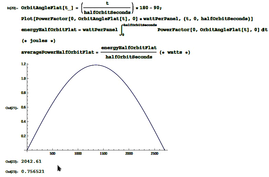
Wes then solves for three possible orientations. Flat orientation is where the TubeSat’s long axis is always facing the direction of travel (the bullet configuration, I’d call it). As it moves through its orbit, it goes from nose-toward-Sun (at one pole) to broadsides at the equator, down to tail-toward-Sun (opposite pole). For flat, “2042 Joules are taken in during the half orbit facing the sun. Over the half orbit period, this equates to an average of 0.75 Watts.”
Radial orientation is where the TubeSat’s long axis always points toward the Earth. The satellite is broadside to the Sun at each pole and has its endcap face the Sun at the equator. Much as with Flat, “2047 Joules are taken in during the half orbit facing the sun. Over the half orbit period, this equates to an average of 0.75 Watts.”
Closing off our analysis by Wes, we have SunSeeker orientation, where the TubeSat is always broadside to the sun and “likely rotating along [its] long axis for cooling.” For this power-optimizing orbital orientation, “3208 Joules are taken in during the half orbit facing the sun. Over the half orbit period, this equates to an average of 1.18 Watts.”
The actual satellite orientation one choses will be based primarily on the sensor requirements. Where you need to point and how you have to face is the primary driver for this. However, once you decide on an orientation, power considerations can kick in. You can rely on the default orientation—simply tumbling and requiring no specific pointing. In our later discussion of sensor loadouts and missions (covered in DIY Instruments for Amateur Space), we discuss different pointings. Once you have a mission pointing, you can run the above power curve calculations.
But pragmatically, assume you will have 15% the maximum potential charging or less on a typical orbit and your power budget will be reasonable.
Get DIY Satellite Platforms now with the O’Reilly learning platform.
O’Reilly members experience books, live events, courses curated by job role, and more from O’Reilly and nearly 200 top publishers.


