Chapter 1. Theory
1.0 Introduction
Although this book is fundamentally about practice rather than theory, there are a few theoretical aspects of electronics that are almost impossible to avoid.
In particular, if you understand the relationship between voltage, current, and resistance many other things will make a lot more sense.
Similarly, the relationship between power, voltage, and current crops up time and time again.
1.1 Understanding Current
Solution
As the word current suggests, the meaning of current in electronics is close to that of the current in a river. You could think of the strength of the current in a pipe as being the amount of water passing a point in the pipe every second. This might be measured in so many gallons per second.
In electronics, current is the amount of charge carried by electrons passing a point in a wire per second (Figure 1-1). The unit of current is the ampere, abbreviated as amp or as unit symbol A.
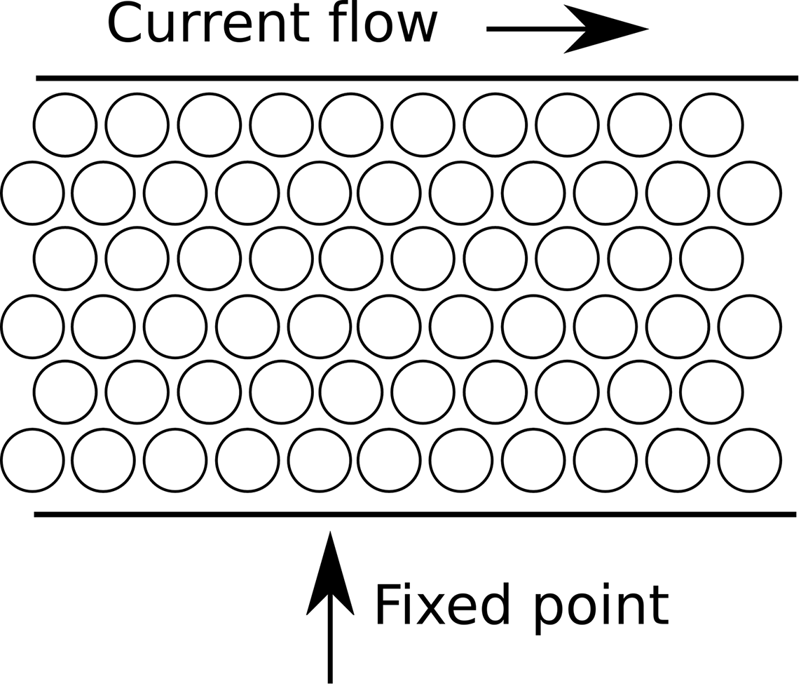
Figure 1-1. Current flowing through a wire
See Also
For a list of units and unit prefixes such as mA, see Appendix D.
To learn more about current in a circuit, see Recipe 1.4.
1.2 Understanding Voltage
Solution
In Recipe 1.1 you read how current is the rate of flow of charge. That current will not flow without something influencing it. In a water pipe, that might be because one end of the pipe is higher than the other.
To understand voltage, it can be useful to think of it as being similar to height in a system of water pipes. Just like height, it is relative, so the height of a pipe above sea level does not determine how fast the water flows through a pipe, but rather how much higher one end of the pipe is than the other (Figure 1-2).
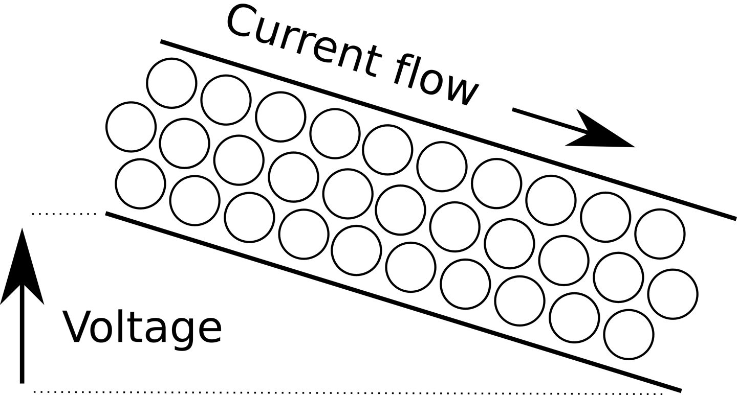
Figure 1-2. Voltage by analogy to height
Voltage might refer to the voltage across a wire (from one end to the other) and in other situations, it might refer to the voltage from one terminal of a battery to another. The common feature is that for voltage to make any sense, it must refer to two points; the higher voltage is the positive voltage, marked with a +.
It is the difference in voltage that makes a current flow in a wire. If there is no difference in voltage between one end of a wire and another then no current will flow.
The unit of voltage is the volt. An AA battery has about 1.5V across its terminals. An Arduino operates at 5V, while a Raspberry Pi operates at 3.3V, although it requires a 5V supply that it reduces to 3.3V.
Discussion
Sometimes it seems like voltage is used to refer to a single point in an electronic circuit rather than a difference between two points. In such cases the voltage then means the difference between the voltage at one point in the circuit and ground. Ground (usually abbreviated as GND) is a local reference voltage against which all other voltages in the circuit are measured. This is, if you like, 0V.
See Also
To learn more about voltages, see Recipe 1.5.
1.3 Calculate Voltage, Current, or Resistance
Solution
Use Ohm’s Law.
Ohm’s Law states that the current flowing through a wire or electronic component (I) will be the voltage across that wire or component (V) divided by the resistance of the component (R). In other words:
If it is the voltage that you want to calculate, then this formula can be rearranged as:
And, if you know the current flowing through a resistor and the voltage across the resistor, you can calculate the resistance using:
Discussion
Resistance is the ability of a substance to resist the flow of current. A wire should have low resistance, because you do not usually want the electricity flowing through the wire to be unnecessarily impeded. The thicker the wire, the less its resistance for a given length. So a few feet of thin wire that you might find connecting a battery to a lightbulb (or more likely LED) in a flashlight might have a resistance of perhaps 0.1Ω to 1Ω, whereas the same length of thick AC outlet cable for a kettle may have a resistance of only a couple of milliohms (mΩ).
It is extremely common to want to limit the amount of current flowing through part of a circuit by adding some resistance in the form of a special component called a resistor.
Figure 1-3 shows a resistor (zig-zag line) and indicates the current flowing through it (I) and the voltage across it (V).
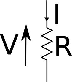
Figure 1-3. Voltage, Current, and Resistance
Let’s say that we were to connect a 1.5V battery to a 100Ω resistor as shown in Figure 1-4. The Greek letter Ω (omega) is used as shorthand for the unit of resistance (the “Ohm”).
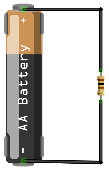
Figure 1-4. Battery and Resistor
Using Ohm’s Law, the current is the voltage across the resistor divided by the resistance of the resistor (we can assume that the wires have a resistance of zero).
So, I = 1.5 / 100 = 0.015 A or 15mA.
See Also
To understand what happens to current flowing through resistors and wires in a circuit, see Recipe 1.4.
To understand the relationship between current, voltage, and power, see Recipe 1.6.
1.4 Calculate Current at Any Point in a Circuit
Solution
Use Kirchhoff’s Current Law.
Stated simply, Kichhoff’s Current Law says that at any point on a circuit, the current flowing into that point must equal the current flowing out.
Discussion
For example, in Figure 1-5 two resistors are in parallel and supplied with a voltage from a battery (note the schematic symbol for a battery on the left of Figure 1-5).

Figure 1-5. Resistors in parallel
At point X, a current of I will be flowing into point X from the battery, but there are two branches out of X. If the resistors are of equal value then each branch will have half the current flowing through it.
At point Y, the two paths recombine and so the two currents of I/2 flowing into Y will be combined to produce a current of I flowing out of Y.
See Also
For Kirchhoff’s Voltage Law, see Recipe 1.5.
For further discussion on resistors in parallel, see Recipe 2.5.
1.5 Calculate the Voltages Within Your Circuit
Solution
Use Kirchhoff’s Voltage Law.
This law states that all the voltages between various points around a circuit will add up to zero.
Discussion
Figure 1-6 shows two resistors in series with a battery. It is assumed that the two resistors are of equal value.
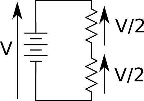
Figure 1-6. Resistors in Series
At first glance it is not clear how Kirchhoff’s Voltage Law applies until you look at the polarity of the voltage. On the left, the battery supplies V volts, which is equal in magnitude, but opposite in direction (and hence sign) to the two voltages V/2 across each resistor.
Another way to look at this is that V must be balanced by the two voltages V/2. In other words, V = V/2 + V/2 or V – (V/2 + V/2) = 0.
See Also
This arrangement of a pair of resistors is also used to scale voltages down (see Recipe 2.6).
For Kirchhoff’s Current Law, see Recipe 1.4.
1.6 Understanding Power
Solution
In electronics, power is the rate of conversion of electrical energy to some other form of energy (usually heat). It is measured in Joules of energy per second, which is also known as a watt (W).
When you wire up a resistor as shown back in Figure 1-4 of Recipe 1.3 the resistor will generate heat and if it’s a significant amount of heat then the resistor will get hot. You can calculate the amount of power converted to heat using the formula:
P = I x V
In other words, the power in watts is the voltage across the resistor (in volts) multiplied by the current flowing through it in amps. In the example of Figure 1-4 where the voltage across the resistor is 1.5V and the current through it was calculated as 15mA, the heat power generated will be 1.5V x 15mA = 22.5mW.
Discussion
If you know the voltage across the resistor and the resistance of the resistor, then you can combine Ohm’s Law and P=IV and use the formula:
With V=1.5V and R of 100Ω the power is 1.5V x 1.5V / 100Ω = 22.5mW.
See Also
For Ohm’s Law see Recipe 1.3.
1.7 Alternating Current
Solution
In all the recipes up to this point, DC is assumed. The voltage is constant and generally what you would expect a battery to supply.
AC is what is supplied by wall outlets, and although it can be reduced to lower voltages (see Recipe 3.9) it is generally of a high (and dangerous) voltage. In the US, this means 110V and in most of the rest of the world 220V or 240V.
Discussion
What puts the alternating in alternating current is the fact that the direction of current flow in AC reverses many times per second. Figure 1-7 shows how the voltage varies in a US AC wall outlet.

Figure 1-7. Alternating Current
The first thing to notice is that the voltage follows the shape of a sine wave, gently increasing until it exceeds 150V then heading down past 0V to around –150V and then back up again, taking about 16.6 thousandths of a second (milliseconds, or ms) to complete one full cycle.
The relationship between the period of AC (time taken for one complete cycle) and the frequency of the AC (number of cycles per second) is:
The unit of frequency is the Hertz (abbreviated as Hz) so you can see that the AC shown in Figure 1-7 has a period of 16.6ms, which is 0.0166 seconds. So you can calculate the frequency as:
You may be wondering why AC from an outlet is described as 110V when it actually manages to swing over a range of over 300V from peak to peak. The answer is that the 110V figure is the equivalent DC voltage that would be capable of providing the same amount of power. This is called the RMS (root mean square) voltage and is the peak voltage divided by the square root of 2 (which is roughly 1.41). So, in the preceding example, the peak voltage of 155V when divided by 1.41 gives a result of roughly 110V RMS.
See Also
You will find more information on using AC in Chapter 7.
Get Electronics Cookbook now with the O’Reilly learning platform.
O’Reilly members experience books, live events, courses curated by job role, and more from O’Reilly and nearly 200 top publishers.

