2.4. Calculating charge impedance
The simulations are done for a quartz torch and for a cold crucible torch, and for different voltage supplies.
2.4.1. Results
The goal of the simulation above is to calculate the equivalent impedance of the torch and inductor.
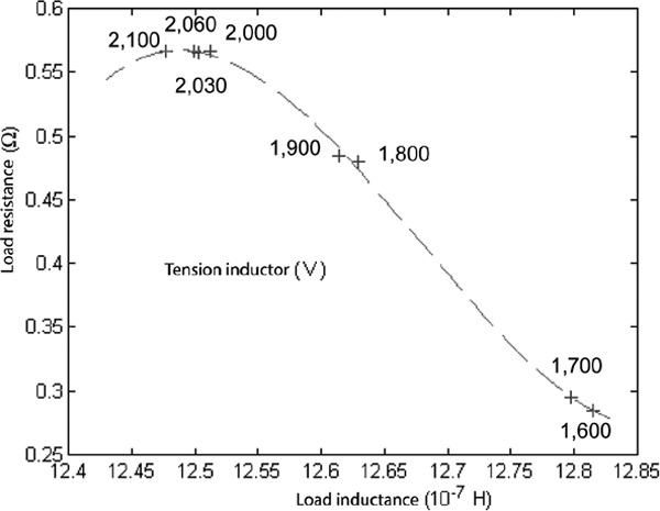
This equivalent impedance is plotted for different inductor voltages Vi, in the presence of a quartz torch and for an argon flow rate of 60 L/min (Figure 2.17). The operating frequency is set to 4.7 MHz. The impedance calculated for a cold crucible torch is shown in Figure 2.18, where the frequency is set to 4.9 MHz.
The load’s equivalent resistance reaches about 0.6 ![]() with either quartz or cold crucible torch. This resistance is mostly the thermal plasma’s. The corresponding inductor voltage is greater with a cold crucible, which results in a worse efficiency for the simulated cold crucible torch.
with either quartz or cold crucible torch. This resistance is mostly the thermal plasma’s. The corresponding inductor voltage is greater with a cold crucible, which results in a worse efficiency for the simulated cold crucible torch.
Figure 2.17. Impedance of an argon plasma as a function of the inductor’s voltage. Quartz tube Argon flow = 60 L/min. Frequency = 4.7 MHz

Figure 2.18. Impedance of the plasma as a function of the inductor’s voltage. Thick cold crucible torch. Argon flow = 60 L/min, ![]() = 4.9 MHz
= 4.9 MHz
Above 2,100 V of inductor voltage, the experiment shows ...
Get Electrothermics now with the O’Reilly learning platform.
O’Reilly members experience books, live events, courses curated by job role, and more from O’Reilly and nearly 200 top publishers.

