This gadget is one of the simplest environmental sensors you can make. All it does is connect an antenna to one of Arduino’s analog ports and output the results as numbers and sounds.
There are some things about this device and how it works that make more sense once you’ve actually created and used it. So we’ve included that information after the build.
- Arduino
- 8-ohm speaker
- 4Char display
- 1-megaOhm resistor
- 3–5 feet of solid core wire
- Battery pack
- Red and black jumpers
We’re going to be using a standard 8-ohm speaker as the output. This is probably the most common kind of hobby audio output, one of the most basic (and oldest) electronic devices.
Simply put, a speaker is an electromagnet connected to a membrane. Variations in an electric current cause the electromagnet to turn on and off. This moves the membrane back and forth, which moves air molecules back and forth, which causes what we call sound.
If the movement is done rapidly enough, and if the voltage signal can be precisely controlled, the speaker will emit sound we can recognize—like music, or a person talking.
Before we begin to build the gadget, let’s be sure the 8-ohm speaker works:
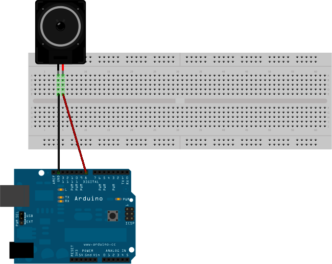
Step 1 Plug your 8-ohm speaker into Arduino, as shown in the breadboard view (Figure 4-1): the red wire into digital pin 8 and the black wire into GND.
Step 2 Find the sketch “ToneMelody” in the IDE at File | Examples | Digital | ToneMelody. Load it onto Arduino and run it.
In the sketch, the header file pitches.h tells the Arduino which audio frequencies correspond to which musical notes. The sketch then includes the data for a little eight-note melody, in two arrays—one containing the notes, and the other containing the duration of those notes. The sketch then plays these tones through Arduino pin 8.
Did you hear a pleasing little melody when you ran the sketch? Then it worked. If not, check your connections, and try again. Make sure that the speaker is plugged into Arduino pin 8 (and not any other pin) and GND.
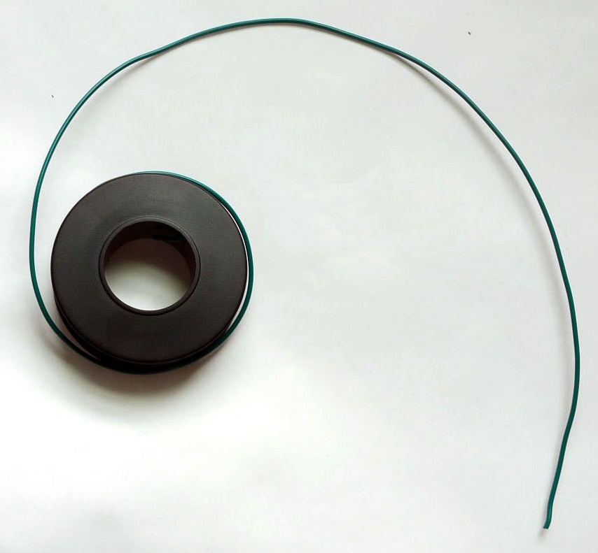
Step 1 Cut a three-foot long piece of solid core wire (Figure 4-2).
Step 2 Strip about 1.5 inches from one end of the core wire.
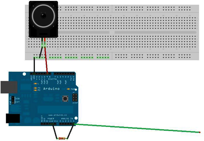
Step 3 Wrap one end of the 1MOhm resistor around the stripped end of the core wire.
Step 4 Insert the wire into analog port A5 on Arduino, and the end of the resistor into GND.
Step 5 Connect one lead of the 8-ohm speaker to digital port 9 on Arduino, and the other lead into GND, as shown in the breadboard view (Figure 4-3).
Step 6 Connect the lead of the 4Char to digital pin 7 on Arduino and the other lead into GND.
Load the following sketch onto Arduino, and you’ve got yourself an EMI detector:
// Arduino Electromagnetic interference detector
// Code modified by Patrick Di Justo, based on
// Aaron ALAI EMF Detector April 22nd 2009 VERSION 1.0
// aaronalai1@gmail.com
//
// This outputs sound and numeric data to the 4char

#include <SoftwareSerial.h>
#define SerialIn 2
#define SerialOut 7

#define wDelay 900

int inPin = 5;
int val = 0;

SoftwareSerial mySerialPort(SerialIn, SerialOut);

void setup()
{
  pinMode(SerialOut, OUTPUT);
  pinMode(SerialIn, INPUT);

  mySerialPort.begin(19200);
  mySerialPort.print("vv");

  mySerialPort.print("xxxx");
  delay(wDelay);
  mySerialPort.print("----");
  delay(wDelay);
  mySerialPort.print("8888");
  delay(wDelay);
  mySerialPort.print("xxxx");
  delay(wDelay);

  Serial.begin(9600);
}

void loop()
{
 val = analogRead(inPin);
 Serial.println(val);
 dispData(val);
 val = map(val, 1, 100, 1, 2048);
 tone(9,val,10);
}

void dispData(int i)
{
  if ((i<-999) || (i>9999))
  {
   mySerialPort.print("ERRx");
   return;
  }
  char fourChars[5];
  sprintf(fourChars, "%04d", i);

  mySerialPort.print("v");
  mySerialPort.print(fourChars);
}Once you have uploaded your sketch to Arduino, and Arduino restarts, you’ll probably hear a cacophony of sound from the speaker, and the numbers on the 4Char display will be so random as to seem meaningless. That’s perfectly all right; they are meaningless.
Because Arduino is connected by a USB cable to your computer, it is receiving a flood of electromagnetic interference from the computer. Even worse, that EMI is being pumped into Arduino via the USB cable.
To make this detector really work, we’ve got to go mobile.
When not operating off the USB cable, Arduino needs a power supply of 7 to 12 volts to work. Anything higher than 12 volts might damage the circuitry; anything lower than 6 volts won’t start Arduino at all.
A fresh 9-volt battery should be enough to get this gadget running.
Step 1 Carefully unplug the Arduino from the USB cable.
Step 2 Snap the power connector to the top of the 9-volt battery, and plug the round end into the power input on Arduino.
Your Arduino should start up normally: the LEDs mounted on the Arduino board should flash, and within a few seconds the EMI code should be up and running.
Get Environmental Monitoring with Arduino now with the O’Reilly learning platform.
O’Reilly members experience books, live events, courses curated by job role, and more from O’Reilly and nearly 200 top publishers.


