Make the Gadget
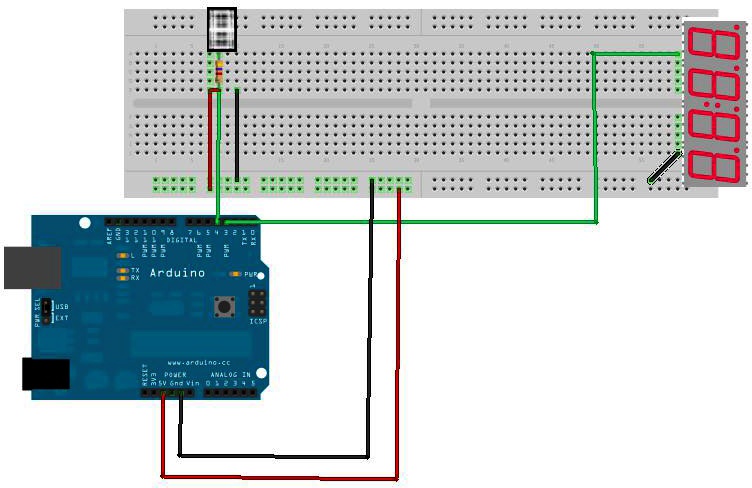
This build has several finicky steps. Look at the breadboard view (Figure 7-2) to see how it all fits together.
Parts
- Arduino
- Ethernet shield
- Breadboard
- DHT-22 sensor
- 4Char display
- 4.7K resistor
- Red and black jumper wires
Breadboard the Circuit
Step 1 Power the breadboard rails.
Step 2 Connect a red jumper wire from the 3.3v pin on the Arduino to the voltage (red) rail on the breadboard, and a black jumper from the GND pin to the ground (black) rail on the breadboard.
Step 3 Connect a short red jumper from the voltage rail to the voltage (leftmost) pin of the DHT-22 temperature and humidity sensor.
Step 4 Connect a short black jumper from the GND rail to the GND (rightmost) pin of the DHT-22.
Step 5 Connect a green jumper from the DATA (second from the left) pin on the sensor to digital pin 4 on the Arduino.
Step 6 Add a 4.7K resistor between the DATA pin of the sensor and the VOLTAGE pin.
Step 7 Connect a green jumper from Arduino pin 3 to the RX (rightmost) pin of the four-character display, and a black jumper from the GND rail to the GND (leftmost) pin of the four-character display.

Figure 7-2. The completed circuit for the temperature-humidity-dew point monitor.
Write the Code
Load the following sketch onto Arduino. You can find it at EMWA GitHub repository | chapter-7 | TempHumidDewpoint.
/* Temperature-Humidity-Dew Point Monitor This sketch gathers temperature and ...
Get Environmental Monitoring with Arduino now with the O’Reilly learning platform.
O’Reilly members experience books, live events, courses curated by job role, and more from O’Reilly and nearly 200 top publishers.

