9Circuit Theorems and Techniques
9.1 Superposition
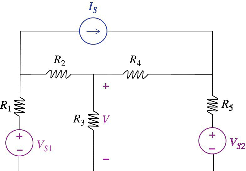
Consider a linear circuit with several independent voltage or current sources, like the one shown in Figure 9.1.

Figure 9.1 Linear circuit driven by several independent sources.
Say, we want to calculate the voltage or current somewhere in the circuit; voltage V across R2 in this case. We could, of course, solve this circuit using the node voltage or mesh current methods discussed previously in Chapter 7.
However, we could also solve this circuit using the principle of superposition (Nilsson and Riedel, 2015, p. 122) which states then whenever a linear circuit is driven by more than one independent source, the response of the circuit can be obtained as the sum of the individual responses due to each independent source acting alone.
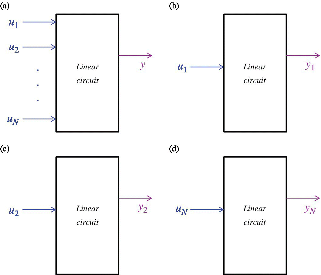
We can think of each independent source as the input to the circuit, and the voltage or current somewhere in the circuit as the output. Then the principle of superposition can be illustrated in block diagram form as shown in Figure 9.2.

Figure 9.2 The principle of superposition.
In Figure 9.2(a) the circuit is driven by several inputs u1 to uN. The output of the system is equal to y. In Figures 8.2(b)–(d), the circuit is driven by one input at time uk, resulting in the corresponding output yk.
According to the principle ...
Get Foundations of Electromagnetic Compatibility with Practical Applications now with the O’Reilly learning platform.
O’Reilly members experience books, live events, courses curated by job role, and more from O’Reilly and nearly 200 top publishers.

