Chapter 4. Advanced Intersect and Follow Me Techniques
The Follow Me and Intersect tools are used together frequently to create complex 3D objects. Follow Me is used to create individual objects by extruding a face along a path, and the Intersect tool is then used to get edges where the Follow Me objects meet themselves or other objects. After these intersection edges are created, trimming is easy.
This chapter offers some advanced techniques for using them in tandem as well as separately. Specifically, you’ll learn to do the following:
Create temporary faces for a Follow Me face
Make round corners
Create lathed shapes
Quickly create a complex roof with a uniform slope
Create “dummy” Follow Me paths when the existing path is not easy to select
Extend Follow Me paths to make intersecting and trimming easy
Use Intersect to create a 3D Follow Me path
4.1. Creating Temporary Faces for Follow Me
Problem
You want to round a sharp corner, but the model contains no face on which you can easily draw a Follow Me face.
Discussion
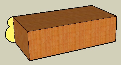
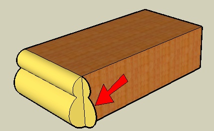
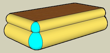
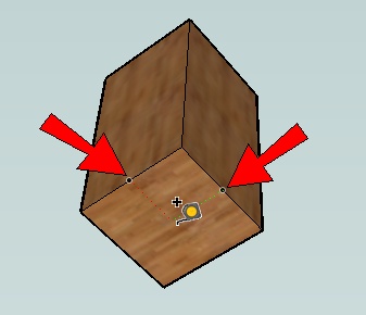
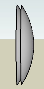
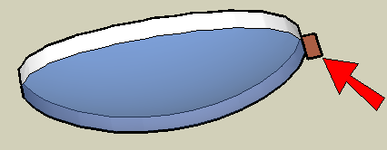
Consider the box in Figure 4-1, which has a Follow Me face (shown in dark brown) drawn on one face.
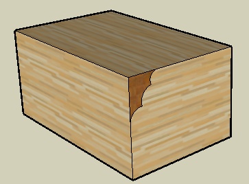
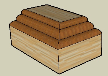
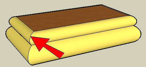
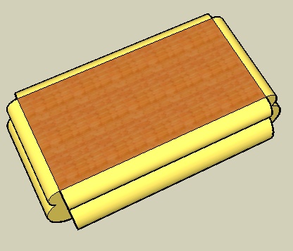
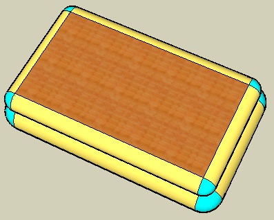
If you use the top face as the Follow Me path, the Follow Me face is extruded around the top of the box, removing volume (Figure 4-2). This example is simple because it was clear where to draw the Follow Me face.
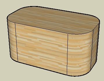
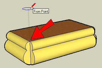
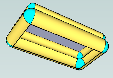
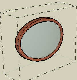
But if you are starting with a box with rounded vertical corners like the box in Figure 4-3, you have no face on which to draw the Follow Me face.
The solution is to create a temporary face on which to draw the Follow Me face. After the Follow Me is complete, you can easily remove the temporary face.
In this recipe’s first example, you’ll start with the model shown in Figure 4-3 and use Follow Me to make a jewelry box with a rounded top. Adding a notch in the box will give you a temporary face for the Follow Me face; you can fill in the notch after the top is rounded. The second example starts with a round object and ends with a round casserole dish with a rounded lid. You’ll get there by creating a temporary face from one of the object’s straight segments.
Example 1: Jewelry Box
In this example, you will round the top edge of a box that has rounded vertical corners.
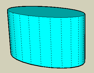
Start with a box with rounded corners like the box in Figure 4-3. You can create your model from scratch, or download my Jewelry Box model from the 3D Warehouse.
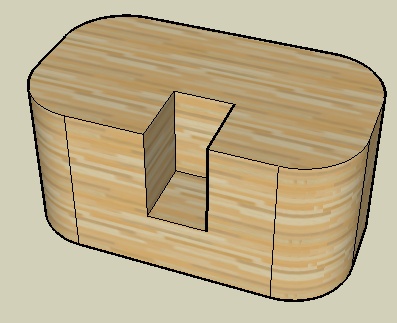
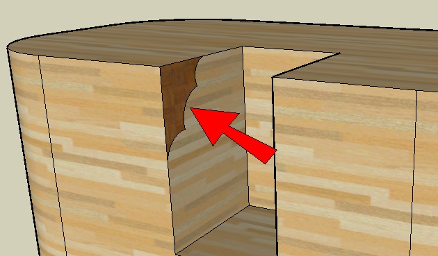
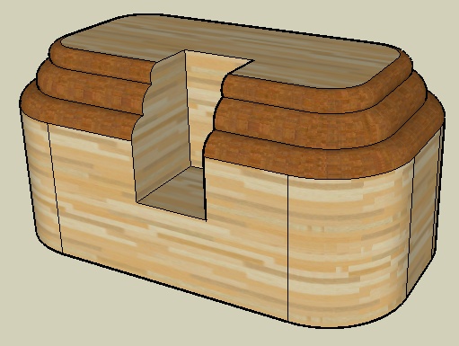
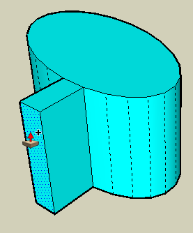
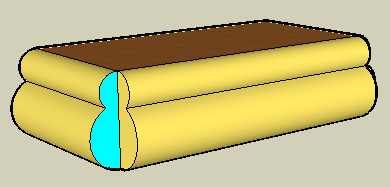
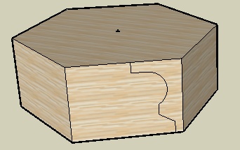
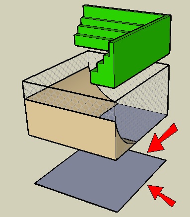
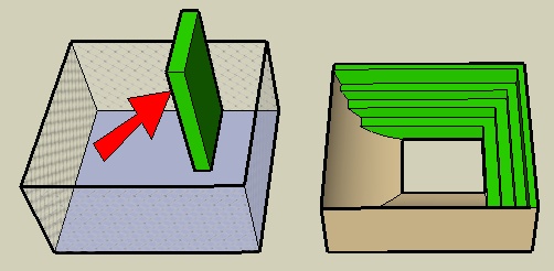
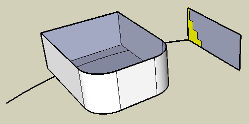
Draw a rectangle on the top or front face and push the rectangle inward, making a small notch (Figure 4-4).
Draw the Follow Me face on one of the vertical faces of the notch (Figure 4-5).
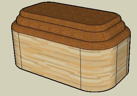
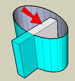
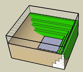
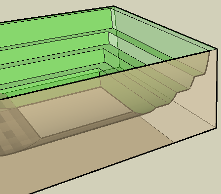
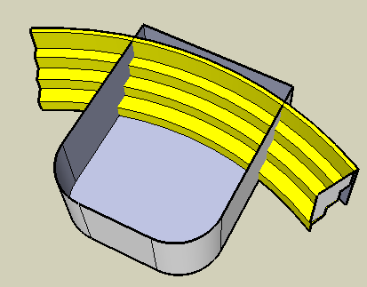
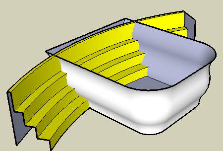
Select the Follow Me path. To do so, you could click each individual edge, but an easier way is to double-click the top face and then Shift-click to unselect the top face plus all four edges that compose the notch. Then use Follow Me to extrude the face around the remaining selected edges (Figure 4-6).
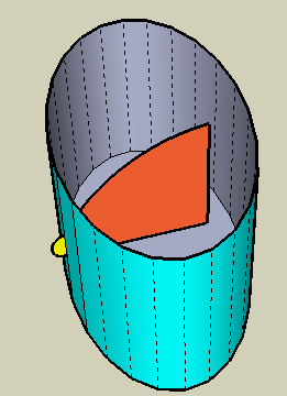
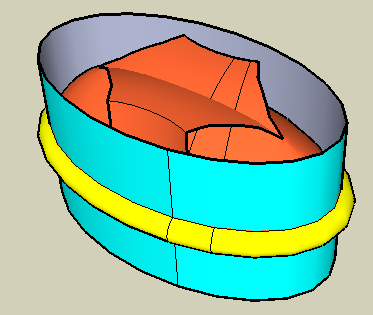
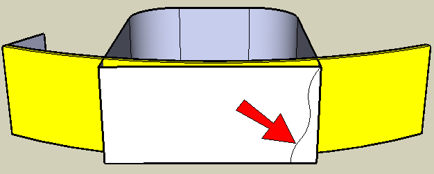
To close the notch, pull one of the side faces of the notch to the other side of the notch. Then erase the extra lines (Figure 4-7).
Example 2: Casserole Dish
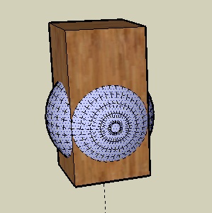
This example also relies on a temporary face for the Follow Me face. Because the main object is round, however, you need to take advantage of hidden geometry in order to create temporary objects.
Start with an oval and pull it up. You can create your model from scratch, or download my Casserole Dish model from the 3D Warehouse.
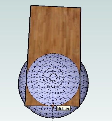
To be able to draw or edit anything on a round face, you need to see the flat segments that compose the face. Choose View→Hidden Geometry to see the dashed lines that indicate where the hidden edges are (Figure 4-8).
Note
If you work with round objects often or hide objects often, it’s helpful to create a keyboard shortcut for the View→Hidden Geometry toggle. I prefer the Function keys (F1, F2, and so forth) for all display commands, which also include Wireframe, X-Ray, and so on. Setting up shortcuts can be done via the Preferences window.
Use Push/Pull with the Ctrl/Option key to pull out one of the segments (Figure 4-9). One of the vertical faces created by this operation will be used to create one of the Follow Me faces.
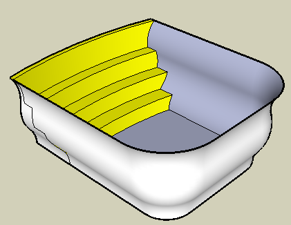
Erase the top face of the oval cylinder and use Push/Pull with Ctrl/Option again to pull out the inside face of this new box. Extend it almost to the other side (Figure 4-10). One of these vertical faces will be used to create another Follow Me face.
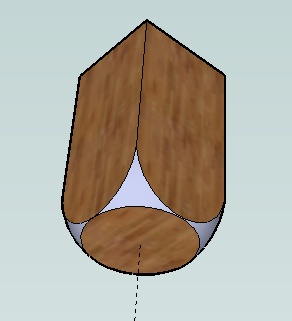
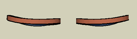
Erase all new faces except for one vertical face on the inside and one vertical face on the outside. Draw a small half-circle face on the outside vertical face (shown in Figure 4-11 in yellow) and a tall arc (shown in orange) on the inside vertical face. The orange face will be used to create the lid, and the yellow face will be used to create the lip around the bottom of the lid. Trim the rest of the temporary vertical faces. If you paint your new faces, be sure to paint both the front and back face, to ensure that the colors will show even if the Follow Me operation reverses the faces.
Hide the hidden edge indicators by toggling the View→Hidden Geometry command.
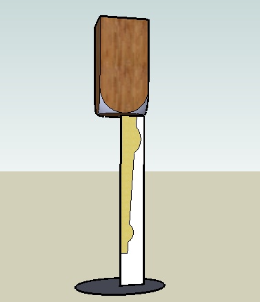
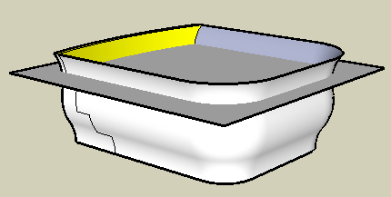
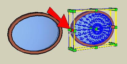
Select the bottom face of the cylinder so that its boundary edges will be used as the Follow Me path, and extrude the half-circle outside the cylinder. Then use the same path to extrude the larger arc face (Figure 4-12).
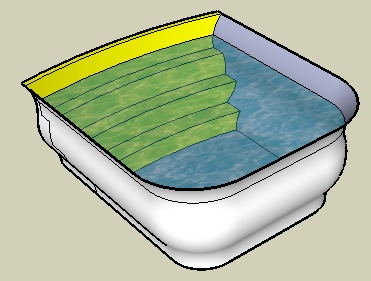
Select everything and use Intersect→Intersect with Model to get edges where the lid intersects itself. Then you can erase all faces above the lid and any extra edges on the lid to get the final dish (Figure 4-13).
4.2. Rounding Corners
Problem
You want to extrude a rounding face around a path with corners, and you want the corners rounded rather than mitered (sharp).
Solution
Use Push/Pull instead of Follow Me, and create separate objects to fill in the rounded corners.
Discussion
Consider a model of a box with a Follow Me face (shown in yellow in Figure 4-14) along one edge.
If you use Follow Me to extrude the face around the top of the box, the corners are sharp, or mitered (Figure 4-15).
If you want these corners to be rounded, you need to use Push/Pull instead of Follow Me to create the straight sections. Then for the rounded parts, use Follow Me with a circular path.
The first example demonstrates how to use this technique to create round corners on the rectangular table shown in Figure 4-15. In the second example, you’ll create similar rounded corners on a hexagonal table, taking advantage of groups to keep existing objects intact after using Follow Me.
Example 1: Rectangular Table
In this example, you will create round corners on a rectangular table with sharp corners.
Start with a model of a table top. Along one edge, add a rounding face (shown in Figure 4-14 in yellow) that will be pulled around the table top. You can create your model from scratch, or download my Table Top model from the 3D Warehouse.
Use Push/Pull to pull the rounding face along one edge (Figure 4-16).
For the next edge, you need to copy the rounding face so that is perpendicular to the edge. Select the front face of the Push/Pull operation you just completed and activate Rotate. Place the protractor at the corner of the table, keeping it oriented to the table top (the protractor’s preview color should be blue). Press Ctrl/Option for copying and make a 90-degree copy (Figure 4-17).
Pull this copied face along the next edge.
Repeat steps 2 through 4 for the remaining two edges of the table (Figure 4-18).
At each corner, you need a rounded version of the rounding face. Therefore, you need to draw a Follow Me circle. This circle must be located away from the table so that it won’t break the table’s geometry. Activate Circle and orient it to the table top (again, the preview color should be blue). Since the circle will be located above this corner, move the mouse directly up, watching for the blue inference line (Figure 4-19).
Make the circle any size you want and be sure to align it to the red or green axis.
To make it easier to copy the round object to other corners later, paint the rounding face a different color (shown in Figure 4-20 in cyan). Because it’s hard to know which side of the rounding face will appear after Follow Me, you should paint the back face too. The easiest way to do this is to right-click on the painted face and choose Reverse Face. (This switches the back and front faces.) Paint the reversed face the same color you just used for the first side. Now this face is painted on both sides.
Use the Follow Me circle as the path for the newly painted Follow Me face, to create the rounded object in the corner (Figure 4-21).
You no longer need the Follow Me circle, so erase it.
Only a quarter of this round object is showing; the rest of it is within the box. But the whole object needs to be copied to each corner. Right-click on the round corner and choose Select→All with Same Material, which selects the entire object. Then copy the round object to each corner (Figure 4-22).
The table top looks fine from the top, but it’s always a good idea to keep your object count low by erasing unnecessary faces and edges. Orbit to see the underside. Because the profile edges at each corner cut the rounding faces, no Intersect operation is needed. Erase faces and edges so that the round borders and corners form an empty shell (Figure 4-23).
To replace the bottom face, trace any edge along the bottom.
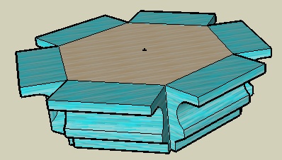
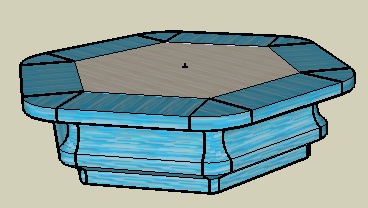
Example 2: Hexagonal Table
This example uses the same Follow Me technique to make rounded corners. To prevent the rounded corner objects from breaking the rest of the table, you will use the grouping technique within Follow Me, which is described in Recipe 2.3.
Start with a hexagon-shaped box and place a point at the center (right-click on the top hexagon edge and choose Point at Center). This point makes it easier to copy objects later.
Note
You can download my Hexagon Table model from the 3D Warehouse, which contains scenes that show the steps for this example.
Draw a rounding face on one vertical face (Figure 4-24).
Copy the rounding face 90 degrees from the vertical face, erase the original, and pull the face along one edge.
Rotate-copy the pulled faces along each side of the hexagon (Figure 4-25).
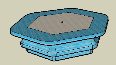
It you were to make a round object for the corner now, using the technique from Example 1: Rectangular Table, the top face of the table would be broken by the top face of the Follow Me object. To protect the existing faces of the table, you need to use a group.
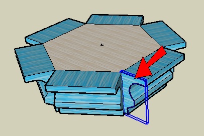
Activate Select and double-click one of the vertical end faces of the pulled rounding faces. This selects both the face and its surrounding edges. Right-click on the face and choose Make Group. The face will then appear with bold edges and surrounded by a bounding box (Figure 4-26).
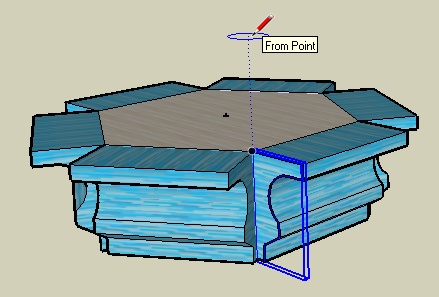
The next step is to draw the Follow Me circle, and it is important that the circle have the correct number of sides. Because this model is based on a hexagon, the number of circle sides should be divisible by six. This ensures that the segments of the circle, and therefore the segments of the resulting round corner, will align with the edges of the Push/Pull faces. Activate Circle and make sure the number of sides is a multiple of six (24 is a good number). As you did for the rectangular table, place the center directly above the corner of the table (Figure 4-27). Do not click yet to complete the circle.
Note
You can set the number of sides of a circle by entering the number before you place the circle’s center point. After you place the center, you can still change the number of sides by typing 24s either before or right after clicking the point along the radius.
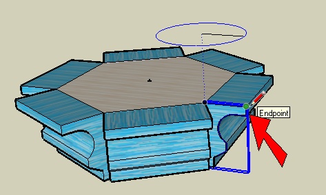
To establish the radius of the circle, click on any point along the top edge of the group. This ensures that a circle segment will start just above the group, so the round Follow Me object will align perfectly with the Push/Pull objects (Figure 4-28).
Use the Edit Group method to make the round object: Select the circle as the path, activate Follow Me, edit the group, and click the face (Figure 4-29).
While the group is still open for editing, run Intersect with Model on the whole group. This creates edges where the group meets the rest of the table. If there are any edges that aren’t created but should be, trace them manually. This is easiest to do with the rest of the model displayed, which can be set in the Components page of the Model Info window. Be sure to check that all edges are drawn, including those on the top and bottom faces of the rounding object.
While the component is still open, open the Components page of the Model Info window to hide the rest of the model, and trim away the extra portions of the group (Figure 4-30).
If you have curved faces with small edges along them, use the Eraser with the Ctrl/Option key pressed to smooth the edges.
Close the group and rotate-copy it to the other five corners (Figure 4-31).
For the final cleanup, select all six groups, right-click on one of them, and choose Explode. Then you can erase the extra edges on the top and bottom of the table (Figure 4-32).
To hide remaining edges along the rounded border, you can select the entire table, right-click, and choose Soften→Smooth Edges from the pop-up menu. Adjust the sliders to smooth the faces.
Note
Another way to create the same table involves offsetting the table top, rounding the sharp corners of this new offset face, and using Follow Me to extrude the rounding face along the new edges. You can download my Hexagon Table Alternative model from the 3D Warehouse, which contains scenes that show the steps for this method.
4.3. Creating Lathed Shapes
Solution
Use Follow Me around a circle to make the lathed shape and Intersect to create the rounded box.
Discussion
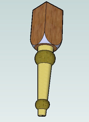
Lathed shapes are a common design element in woodworking and furniture design, and a table leg is perhaps the most common lathed shape. Two steps need to be completed for this model:
Create the rounded box to house the leg, which is modeled by using Intersect.
Create the lathed shape itself, which is done by extruding a face around a Follow Me circle.
In this recipe, you’ll create the box first and then work your way down to complete the leg.
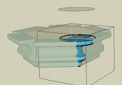
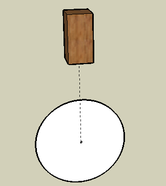
Start with a square and pull it up.
Because the rest of the table leg will be created relative to the center of this box, you need to mark the center with a construction line. Activate Tape Measure and start the construction line on the bottom of the box, where the red and green directions meet from adjacent midpoints (Figure 4-33).
Draw the construction line straight down.
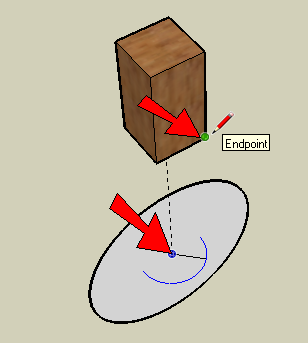
Draw a vertical circle centered on the construction line endpoint (Figure 4-34).
Because the box corners are to be rounded evenly, the rounding must be based on a sphere whose extents meet the box corners. So draw a horizontal circle, perpendicular to and concentric with the large circle. The number of sides should be a multiple of four, because the circle has to align with the four corners of the box. To establish the radius, click on a corner of the box above the circle (Figure 4-35).
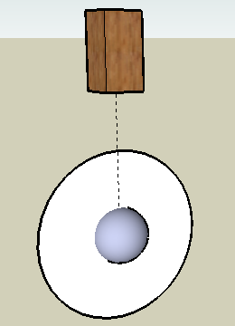
To create the sphere, select the larger circle as the Follow Me path and use Follow Me on the smaller circle (Figure 4-36).
Move the sphere straight up into the middle of the box.
Leave the sphere selected. The next step is to move the sphere back down so that the rounding of the corners will start from the base of the box. In order to see how to move the sphere, choose View→Hidden Geometry from the main menu, which displays the dashed lines indicating hidden edges (Figure 4-37).
Move the sphere straight down so that the lowest point on any of the protruding sides meets the midpoint of a lower edge (Figure 4-38). This establishes the corners of the box that need to be trimmed.
Turn off the display of hidden edge indicators by choosing View→Hidden Geometry again. Run Intersect with Model, and trim both the box and sphere (Figure 4-39). Check the model in X-Ray or Wireframe view to erase all extra edges.
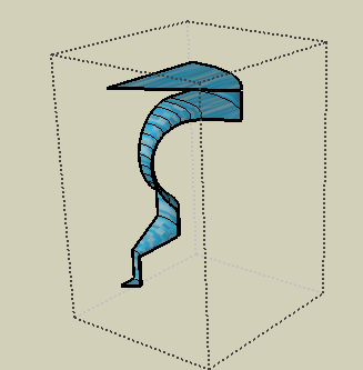
To make the lathed shape, draw a vertical rectangle below the box, sharing an edge with the construction line. On this rectangle, draw a section for the leg, like the one shown in Figure 4-40 in yellow. For the Follow Me circle, draw a horizontal circle at the bottom of the rectangle, centered on the construction line.
Use Follow Me to extrude the leg section around the circle. Then erase the circle and trim the rectangle, as shown in Figure 4-41.
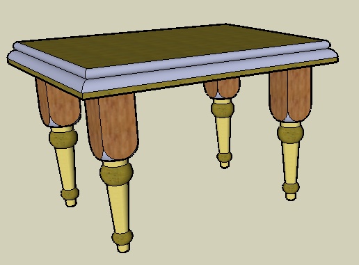
Make the leg a component and make three more copies to support a table.
For the table top, draw a rectangle on top of the set of four legs. Offset the rectangle outward and pull it up. To make the table top more interesting, you can also extrude a Follow Me face around the table top (Figure 4-42).
4.4. Roofing with a Uniform Slope
Solution
Draw the roof section, use Follow Me to extrude the section along the building edges, and use Intersect to trim the roof.
Discussion
Roofs can be a difficult part of building design, but by combining Follow Me and Intersect, you can quickly make a complex-looking roof. There are three basic steps:
Draw a face to represent the roof section with the correct slope.
Use Follow Me to extrude the face around the building.
Use Intersect with Model to get edges where the roof faces meet themselves, and trim the extra edges.
Use this technique when you want the same roof slope all around the building. To demonstrate, this recipe uses the technique on a simple roof with a known slope. In the Other Uses section, you’ll see more complex roofs created using the same technique.
Note
Other roofing solutions are discussed in Chapter 5.
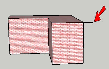
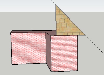
Start with an L-shaped building.
To start the roof section, draw a short horizontal line from the top corner of one of the front faces (Figure 4-43).
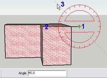
The Protractor tool (Tools→Protractor) is used to create an angled construction line at a known angle from an existing edge. Activate Protractor and click points 1 and 2 in Figure 4-44 to set the baseline for the construction line along the top of the building. Then move the mouse up and click point 3 to create the construction line at a 45-degree angle. (You can look for this angle in the Angle field, or type 45 and press Enter.)
Note
Even though the field at the bottom of the window is labeled Angle, you can also enter a roof pitch in the rise-run format. For example, an 8/12 slope is entered as 8:12.
Use the construction line to create the triangular roof face as shown in Figure 4-45. The face should extend past the midpoint of the front face, so that the profile will not fall short of the center of the widest part of the building.
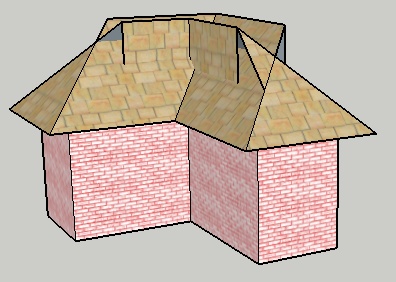
Select the top face of the building as the Follow Me path. Then use Follow Me to extrude the roof face around the building (Figure 4-46).
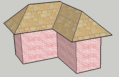
Select the entire roof and run Intersect with Model to get the edges where the roof intersects itself. Then trim away the extra edges (Figure 4-47).
Even when the roof looks “clean,” you should check your model in X-Ray or Wireframe mode to erase any extra edges inside the roof.
Other Uses
This section contains two examples of more complex roofs, created using the same Follow Me and Intersect technique. The first example is an overhanging roof, and the second uses curved faces on both the building and roof.
Overhanging roof
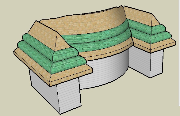
Figure 4-48 shows a house with a thick, overhanging roof. The roof is based on a 2D Follow Me face, which is extruded around the top face of the building. The resulting roof faces are intersected and trimmed.
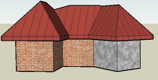
To see how it’s done, download my Overhanging Roof model from the 3D Warehouse.
Curved faces on the roof and building
Figure 4-49 shows a building with curved faces, and a roof section that also has curves. The easiest way to create a roof section like this is to first create a vertical face on which to draw the roof section. After running Follow Me and Intersect with Model, the trimming of extra edges can take a while. But the results are worth the effort.
To see how it’s done, download my Curvy Roof model from the 3D Warehouse.
4.5. Creating “Dummy” Follow Me Paths
Problem
You want to intersect two sets of faces created by Follow Me, but you’re having trouble defining and selecting paths.
Solution
Copy the edges needed for the path so that the path can easily be selected away from the rest of the model. Alternatively, move the Follow Me faces away from each other so that their paths can easily be identified and the resulting faces won’t interfere with each other.
Discussion
The problem discussed in this section deals with different Follow Me faces that are extruded around edges of the same shape. In these cases, you might have difficulty selecting a path in advance, particularly if edges are broken by other operations. The solution is to copy a set of edges elsewhere so that they can be easily selected. Another problem encountered in the same model is that two sets of Follow Me faces within the same closed shape can interfere with one another. The solution here is to temporarily move one of the faces away, run Follow Me on it, and then move it back into place. After all faces are in place, they can be intersected and trimmed.
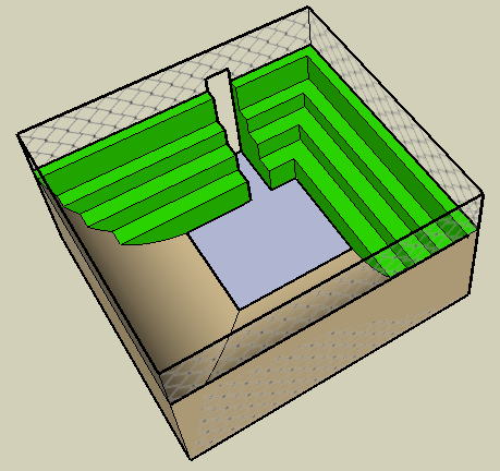
The main example that will demonstrate these techniques is a skate park, in which two Follow Me faces create the skate ramp and the spectator seating. In Other Uses, you will see the same technique applied to a picture frame.
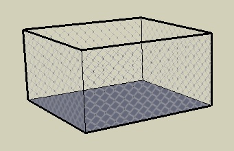
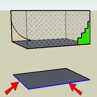
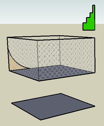
Start with a box and remove the top. Paint the four sides with a material from the Fencing material category (Figure 4-50). Many of these fencing materials have alpha transparency, which means the white background of each image is interpreted by SketchUp as transparent.
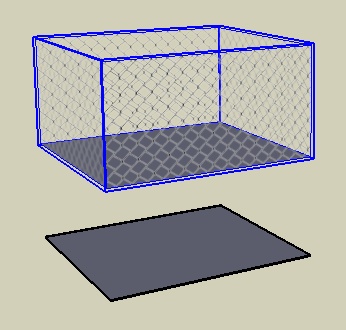
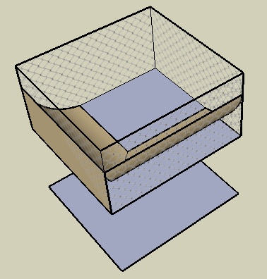
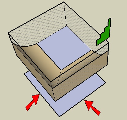
Make a copy of the bottom of the box, straight up or down. The edges around this face will be the “dummy” paths.
Select the original box (not including the copied face) and make it a group (Figure 4-51). This is so that the fence faces won’t be broken when objects are added inside the box.
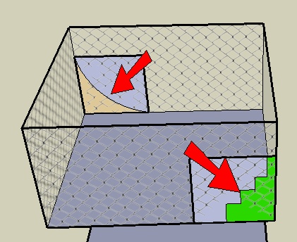
Using the faces of the box group to draw on, draw two identical rectangles in opposite corners on which to make the Follow Me faces. On one face, draw an arc section for the skate ramps (shown in Figure 4-52 in beige) and on the other, draw a section for steps (shown in green).
Trim the extra edges from these faces.
Because the fence box is a group, you can’t select edges within it to define a Follow Me path. So you’ll use the edges of the face you copied from the bottom of the box. Select the two edges of the face shown in Figure 4-53.
With this path defined, run Follow Me on the arc face. Here you can see the second problem: the Follow Me faces interfere with one another. The arc faces were not completed, and the face with the steps has disappeared (Figure 4-54).
Undo the Follow Me.
Move one of the Follow Me faces to a location directly above the box. I chose to move the section for the steps, as shown in Figure 4-55.
Use the two edges indicated in Figure 4-56 as the Follow Me path for the arc face.
Use the other two edges as the Follow Me path for the steps (Figure 4-57).
Move the steps back down inside the fence (Figure 4-58).
Note
If you don’t want to bother moving up and down, you could have made the arc and step sections into groups. Then you could use the Edit Group method within Follow Me, without having to move anything. But you would have to Explode both groups before intersecting.
You could also make just one of the sections a group.
Hide the fence group and run Intersect with Model on the arcs and steps. Then trim away all the extras. Check in X-Ray or Wireframe mode to be sure all extra edges are erased (Figure 4-59).
Bring the hidden group back.
The hard part is finished, but you can make this model a little more usable. There’s no way to get in or out of this park, so an entrance is needed. First, move the ramps and steps out of the group and add a cutting shape inside the group (Figure 4-60).
Move the ramps and steps back inside, intersect them, and trim away the entrance. To cut a hole in the fence, edit the fence group and add a tall rectangle for an opening. Then erase the opening face. Figure 4-61 shows the result.
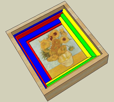
Other Uses
You can use the same technique to create an interesting picture frame. In this example, you would copy the inside face of the frame for the dummy paths, and you would move one of the Follow Me faces above or below the model. After Follow Me is complete for both faces, move everything back into place, intersect, and trim (Figure 4-62).
Note
Using graphics in your model is covered in Chapter 9.
4.6. Extending Follow Me Paths
Problem
You want to trim two sets of Follow Me objects, but you want to be sure there will be enough of an overlap for trimming purposes.
Solution
Extend the Follow Me paths past where they need to be.
Discussion
Using extended Follow Me paths results in Follow Me objects that extend past the faces they are supposed to intersect. This ensures that all faces and edges of the Follow Me objects are long enough to intersect, and it makes trimming after intersection easy.
The main example uses the extended path technique to create a hot tub with curved walls and steps leading down into the tub. The paths for both the tub steps and the curved walls extend past the final limits of the tub, so that extra faces are easy to trim.
In the Other Uses section, the same technique will be applied to window frames.
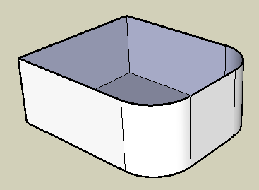
Start with a box with two rounded corners and no top face (Figure 4-63).
In Top view, draw an arc on the ground plane, which extends past both sides of the box (Figure 4-64). This path will be used to create the steps that lead down into the tub.
Copy one of the side faces of the box to the end of the arc. On this face, draw a cross-section for steps (Figure 4-65).
Using all three segments of the arc as the Follow Me path, and the step section as the Follow Me face, create the steps (Figure 4-66).
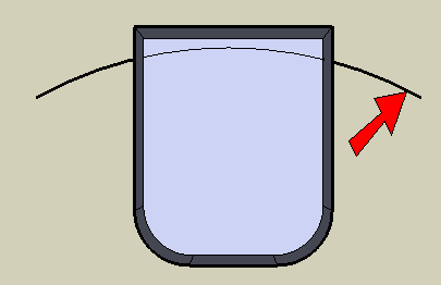
On the back of the box, make a face like the one indicated in Figure 4-67, using tangent arcs.
The Follow Me path for this face is another extended path, going past the back of the tub steps, so the curved walls will be easy to trim behind the steps. Select all of the top edges of the box as the Follow Me path (not including the edge along the back face) and run Follow Me on this face. This creates the curvy walls of the hot tub. If you have extra vertical faces around the tub, erase them (Figure 4-68).
Run Intersect with Model on the entire model, and trim the walls and steps that extend past each other (Figure 4-69). Because the paths for these objects were extended, trimming is easy.
The last step is to fill the tub with water. The easiest way to make a face to represent the water level is to make a simple box next to the hot tub, at the height you want for the water. Remove all but the top face of this box, and move edges until they intersect the tub (Figure 4-70).
Intersect and trim. You can paint this face with a translucent water material from the Water category (Figure 4-71).
Other Uses
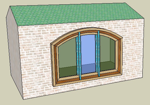
The extended path technique can be applied to window frames. This section shows two examples of such windows: a stained-glass window that you might see in an old church and a more modern three-paned window.
Stained-glass window
Figure 4-72 shows windows whose frames have two parts, created using two separate Follow Me faces. The Follow Me paths are extended past one another, and each Follow Me face is a group. After both Follow Me face groups are extruded along their paths, they are exploded, intersected, and trimmed. After the window is made into a component that cuts walls, it can be inserted into walls.
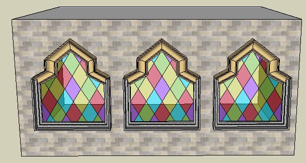
To see how it’s done, download my Stained Glass Window model from the 3D Warehouse.
Three-paned window
Figure 4-73 shows a window with three panes. The window frame is created using Follow Me on the frame face. The muntins separating the panes are created with a simple Push/Pull, starting and ending past the window frame. Intersect and trim, make the window a component, and insert.
To see how it’s done, download my Three Paned Window model from the 3D Warehouse.
4.7. Using Intersect to Create a 3D Follow Me Path
Problem
You want to use Follow Me along a 3D path, but it is difficult to draw the path.
Solution
Use the Intersect tool to create the path.
Discussion
Recipe 2.7 demonstrated how to use grouped reference geometry to create a 3D Follow Me path. This recipe presents another technique for creating a 3D path, in which intersection edges between two objects create the Follow Me path. This technique is helpful in cases where reference geometry is not easy to draw, but you do know the basic 3D parameters of the path.
In this recipe, you will model a pair of glasses. The frame around each lens proceeds along a 3D path, which is the intersection of a partial sphere and the frame shape. In the Other Uses section, the same technique is used to create a window frame around a curved window.
Create the Lens
This section demonstrates how to intersect two objects to produce the 3D Follow Me path. You’ll create one lens for the glasses, whose border edges form the 3D path.
In Top view, use Arc and Line to make a face (Figure 4-74).
Make a vertical circle centered at the line’s midpoint (Figure 4-75).
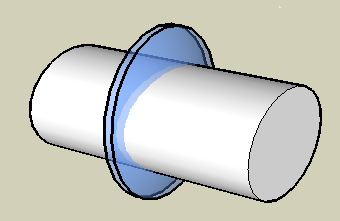
Use the large circle as the Follow Me path for the lens face. After you run Follow Me on the lens face, you will have a partial sphere. Erase the circle. What remains is the curved glass from which the lens will be cut (Figure 4-76).
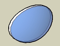
To give the lens glass some thickness, make a copy of it slightly in front or behind (Figure 4-77).
Paint the lens glass with a translucent material.
In Front view, in some blank space next to the lens, draw a shape for the lens frame (Figure 4-78). My frame is a simple oval (created by using the Scale tool on a circle), but you could use a rectangle with rounded corners, a star, or whatever shape you want.
Pull out the lens shape and move it into the lens glass (Figure 4-79).
Intersect and trim (Figure 4-80).
Make the Lens Frame
The border around the front of the lens will be used as the 3D path, and this path will be used to create the frame.
On one side of the lens, draw a shape to use as the Follow Me face for the frame (Figure 4-81). My Follow Me face is a rectangle, but you could try a curved shape.
To prevent the Follow Me frame from breaking the lens, make the Follow Me face a group.
You know that when a face is 2D, you can select it to define its boundary as the Follow Me path. But when the path is 3D, you need to select the Follow Me edges, and not the face. To select the edges bordering this face, double-click the front face of the lens and then Shift-click to unselect the face. This leaves only the edges selected.
Run Follow Me on the frame shape group. To remove the little edges throughout the frame, select everything inside the group, right-click, and choose Soften→Smooth Edges. Adjust the sliders until the edges disappear (Figure 4-82).
Close the frame group.
To make the second lens and frame, copy the framed lens next to the original and leave the copy selected.
To ensure that the pair of glasses is symmetric, activate Scale, which will be used to turn the copy inside-out. Click the drag handle in the direction you want to scale (Figure 4-83).
For the scale value, enter −1. Then move the copy so that the spacing between the lenses looks correct (Figure 4-84).
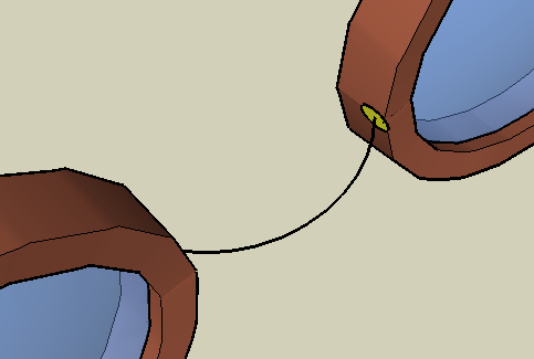
To make the nosepiece, add an arc between the frames, plus a small Follow Me face (Figure 4-85). Because the frames are grouped, these new objects don’t stick to them.
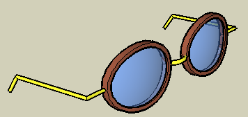
Finish the nosepiece and make the ear pieces the same way: Use Follow Me and then make an inside-out copy. The completed pair of glasses is shown in Figure 4-86.
Other Uses
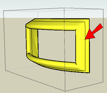
This technique can be used to add a frame to a curved window.
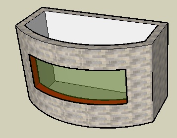
The method to create the window itself is described in Recipe 3.4. In the example in Figure 4-87, the window glass is along the front of the window, not the back or middle. This makes it easier to define the path for the frame. The window itself is a component.
Edit the window component and add a shape for the frame (shown in Figure 4-88 in yellow). Make the frame shape a group.
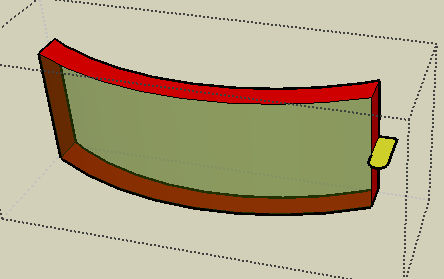
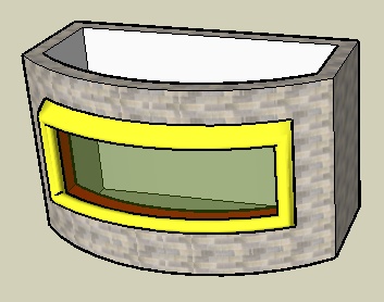
Extrude the frame around the border of the glass and smooth the edges. Run Intersect with Model on the frame, to get the edges where the frame meets the walls of the building (Figure 4-89).
Trim the frame, close the frame group, close the window component, and you have a window with a curved frame (Figure 4-90).
Get Google SketchUp Cookbook now with the O’Reilly learning platform.
O’Reilly members experience books, live events, courses curated by job role, and more from O’Reilly and nearly 200 top publishers.

