Chapter 1. Building a Bench: Your First SketchUp Model

At first glance SketchUp doesn’t look much different from other programs you use to work with photographs, drawings, or even words. You have menus, toolbars, and a large work area. The difference, of course, is that SketchUp’s work area is a window into a three-dimensional world where you can build just about anything. It can be as big as the Empire State building or as small as an iPod. By using SketchUp you can design your new beach house inside and out, and build all the furniture for each room. It’s your world, and this chapter is your first-class introductory tour.

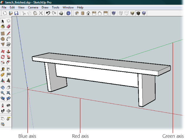
In the first part of this chapter, you’ll learn about SketchUp’s menus, tools, and the drawing window. You’ll see how to customize your workspace to make it easier to follow along with the exercises in this book. The rest of this chapter describes how to build a simple bench made from just four pieces of wood, as shown in Figure 1-1.

Tip

If you’d like to see how the finished bench looks in SketchUp, you can find the document file bench_finished.skp at http://missingmanuals.com/cds.

Even though the bench is simple, the step-by-step exercises introduce many of SketchUp’s drawing and navigation tools. You’ll get a taste of how much fun it is to push and pull your 3-D drawings into shape. You’ll also learn some valuable techniques for navigating a 3-D workspace and for moving and aligning 3-D objects. Don’t worry if it seems that the exercise moves quickly. In later chapters, you’ll see the concepts introduced here explained in much greater detail. In fact you’ll see references along the way that point to more detailed explanations. So if you’re ready for a fast-paced tour of SketchUp, grab your virtual sculptor’s chisel and follow along.

The steps in this chapter describe how to build this simple bench in SketchUp. Three colored axes help you keep your orientation in the workspace. In this image the red axis in front of the bench runs from left to right. The blue axis runs up and down. The green axis runs from the front of the image to the back.
Figure 1-1. The steps in this chapter describe how to build this simple bench in SketchUp. Three colored axes help you keep your orientation in the workspace. In this image the red axis in front of the bench runs from left to right. The blue axis runs up and down. The green axis runs from the front of the image to the back.

Firing Up SketchUp for the First Time

After you first install SketchUp (Installing SketchUp), you start it just like you would any program. For Windows computers:

  • Go to Program Files → Google → Google SketchUp 7, and then double-click the program’s icon.

  • Click Start → All Programs → Google SketchUp 7.

  • Click Windows → Recent Items, and then click a SketchUp (.skp) document.

If you’re of the Mac persuasion:

  • Go to the Applications → Google SketchUp 7 folder, and then double-click the program’s icon.

  • Drag the SketchUp icon from the Applications → Google SketchUp 7 file to the Dock. Once that’s done you can always start the program from there.

  • Choose → Recent Items → Google SketchUp 7.

You can always double-click any SketchUp document to start up SketchUp and open that document. That’s probably the easiest way to start SketchUp on any platform.

At first, every time you start the program, SketchUp greets you with a “welcome” window. This window includes a few subpanels, which vary depending on whether you’re running SketchUp 7 or SketchUp Pro. Both versions, though, display Learn and Template subpanels. SketchUp Pro also shows a License subpanel. The purpose of the Learn panel is to introduce some basic SketchUp concepts. After a quick introductory animation, you can click links to “Watch more videos” or “Read the documentation”. The Template subpanel holds several preformatted documents that you can use to get a head start on your project. For example, if you’re beginning a furniture or woodworking project (as shown later in this chapter), click the “Product Design and Woodworking – Inches” template. If you grow tired of the welcome window popping up every time you run SketchUp, turn off the “Always show on startup” box in the lower-left corner.

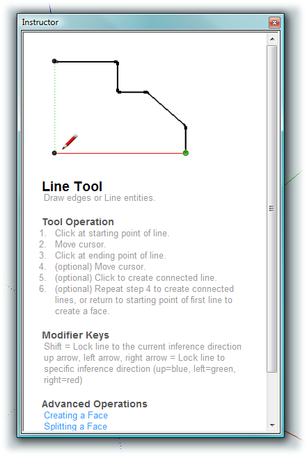
The other window that appears when you first start SketchUp is the Instructor window (Figure 1-2). This clever feature provides quick visual and written tips on how to use whatever tool you’ve selected. When you’re first starting out, the Instructor tips can be pretty helpful. If you’ve had enough, you can close the window by clicking its close button. (You can always bring it back with Window → Instructor. Use Help → Welcome to SketchUp to show the welcome window.)

The Instructor window knows what tool you’re using and provides an animated demo complete with step-by-step instructions for using the tool.
Figure 1-2. The Instructor window knows what tool you’re using and provides an animated demo complete with step-by-step instructions for using the tool.

A Tour of SketchUp’s Main Window

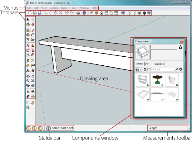
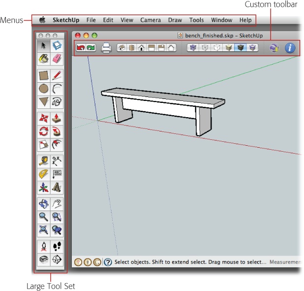
Once you’re past the Learning Center, you see the main window. You use its five main areas when you’re building in SketchUp (Figure 1-3):

  • Menus. Just as in your word processor, you get menus and submenus that give you access to SketchUp’s tools and commands.

  • Toolbars. Click an icon in a SketchUp toolbar, and you’ve got a new tool in hand. SketchUp has several different toolbars that you can show, hide, or drag around the workspace. In Windows, you can reach toolbar central by going to View → Toolbars, where you see over a dozen toolbars that you can show or hide with a mouse click. On a Mac, choose View → Tool Palettes. You have as many toolbars to choose from, but Macs have their own nifty toolbars. Control-click on the top of the SketchUp document window and choose Customize Toolbar. A window opens with all of SketchUp’s tool buttons. Drag buttons on and off the toolbar to customize your workspace.

    Note

    Toolbars are one of the areas where the Windows and Mac versions of SketchUp appear slightly different. Most of the differences, though, are in the program’s appearance rather than function.

  • Drawing area. The main portion of the SketchUp window is devoted to your drawing area. Think of it as your camera’s view of a 3-D world.

  • Status bar. In the lower-left corner is the status bar. Like a friend of few words, the status bar’s Hint tool gives you facts related to the tool and job at hand. If you need a hint about what to do next, look to this corner. For more verbose instructions, click the question-mark button to open the Instructor window (Figure 1-2).

    The latest version of SketchUp added three new buttons to the status bar. From left to right they display geographic references (in Google-speak, it’s called georeferencing; see Using Google Earth to Set Geographic Locations for details), credits (the model or component’s designer), and the Google account login.

  • Measurements toolbar. Previously known by SketchUp fans as the Value Control box (VCB), this humble-looking box is magic. You use it to enter the dimensions of objects or the distance you want to move something, but that only scratches the surface. Once you learn how smart and versatile the Measurements toolbar is, you’ll be a fan, too.

Note

Traditionally, the Measurements toolbar appears in the lower-right corner of SketchUp. But it can also be displayed some other ways. In Windows, choose View → Toolbars → Measurements, and SketchUp produces a toolbar that can float anywhere on your screen and that you can dock at any edge of the window. On Mac, when you customize your toolbars (For Mac), you can place the Measurements toolbar at the top of the Document window.

The SketchUp workspace has five main areas. SketchUp also has a number of windows that you open from the Window menu. Like the Components window shown here (and described fully on ), these windows give you access to additional tools, settings, and prebuilt models from the Taj Mahal to a kitchen sink.
Figure 1-3. The SketchUp workspace has five main areas. SketchUp also has a number of windows that you open from the Window menu. Like the Components window shown here (and described fully on Exploring the Components Window), these windows give you access to additional tools, settings, and prebuilt models from the Taj Mahal to a kitchen sink.

In addition to the five main workspace parts, SketchUp uses several different windows, such as the Components window that’s open in Figure 1-3. You can open and close them as needed by using the Window menu. With the tools in these windows, you’ll apply color and shading to your models, select prebuilt components, add shadows and lighting effects, and organize your project.

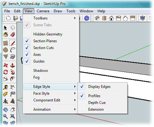
SketchUp’s menu bar is stocked with the usual suspects, such as File, Edit, Window, and Help. SketchUp’s View menu is a little different from the ones in most programs (Figure 1-4). The View menu lists items in the SketchUp window that you can show or hide, including things like drawing guides, axis lines, measurement marks, and even different toolbars. If you’re looking for tools that change your view of the drawing window, such as a Zoom or Pan tool, look under the Camera menu.

The View menu controls what items are visible or hidden in the SketchUp drawing area. Items with checkmarks are visible. To hide an item that’s checked, just click the item in the menu.
Figure 1-4. The View menu controls what items are visible or hidden in the SketchUp drawing area. Items with checkmarks are visible. To hide an item that’s checked, just click the item in the menu.

Looking Around with the Camera

The concept behind SketchUp’s camera is that the drawing area is your view of a 3-D world. Imagine you’re a movie director, you’ve set up your camera, and the drawing area is your view through the camera. Want to see a different view? Move the camera. For example, in Figure 1-1, you have a front view of the bench. To view the bench from above, you use the command Camera → Standard Views → Top. For a side view, you can use Camera → Standard Views → Right (or Left).

When you make these changes, you’re moving the camera view. You’re not moving the bench. It’s remaining in the same place. When you use some of the tools from the toolbar such as the Orbit or Pan tools, there’s a tendency to think that you’re moving objects in the 3-D world when actually it’s just your viewpoint of the world that’s changing.

Tip

In SketchUp, the mouse is your primary building tool, so it helps to have a mouse that plays well with SketchUp. Whether you’re working in Windows or Mac, it’s more convenient to have a three-button mouse, where the middle button is a scroll wheel. You can use that middle button to easily move around the drawing window without disrupting your work in progress. For Mac users, the standard Mac mouse with the roller button doesn’t work quite as well with SketchUp as it should. You may want to invest in a cheapo three-button mouse to use with SketchUp.

Customizing Your Workspace

The folks at Google don’t want to overwhelm you with too many tools and options when you’re just starting out. In both the Mac and Windows versions of SketchUp, your first view shows a minimum number of tools. This tool set is officially dubbed the Getting Started tool set. However, to work along with the exercises in this book, you may as well make a few changes so your SketchUp workspace matches the pictures in this book. The suggestions in this section display, with a minimum of onscreen clutter, the tools you’ll use most often and will save you from digging into a lot of menus to find commands. You can always change them later as you adjust to working in SketchUp. When you add or remove toolbars, SketchUp remembers those changes even after you close the program.

For Windows

Follow these steps, and your Windows version of SketchUp will look like Figure 1-3. If you’re a Mac fan, skip to the next section and set up your workspace to match Figure 1-5.

  1. Choose View → Toolbars → Large Tool Set.

    A new toolbar appears with buttons running vertically down the left side of the window. This new toolbar includes all the tools that are in the Getting Started toolbar, so in the next step, you’ll hide the Getting Started toolbar. Initially, the large toolbar is attached to the drawing area, but by clicking the bar at the top, you can drag it away from the drawing area to create a floating toolbar.

  2. Choose View → Toolbars → Getting Started.

    Before you click, checkmarks are next to both the Large Tool Set and the Getting Started options. In the View menu a checkmark indicates that an option is visible in your workspace. Clicking a checked item hides it from view and removes the checkmark.

  3. Choose View → Toolbars → Standard.

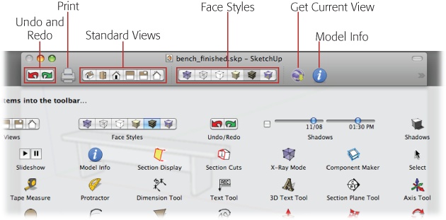
    The Standard toolbar provides the tools that you find in almost every program, though the buttons look a little different. These buttons let you create, open, and save SketchUp files. You also see Cut, Copy, Paste, and Erase buttons. In the next group, you see Undo and Redo arrows. Bringing up the rear is a Print button. Last but certainly not least is a button that’s unique to SketchUp. The blue circle with the letter i is the Model Info button, which provides juicy tidbits about the model you’re building.

  4. Choose View → Toolbars → Views.

    When you work in 3-D, you change views frequently; or from the “SketchUp think” perspective, you move the camera. For example, suppose you want to make sure your model is fitting together properly. Sometimes the only way to see whether a gap exists between two objects is to view them from a different angle. The six view buttons get a lot of use. The Camera Standard Views buttons are Iso (short for isometric or angled view), Top, Front, Right, Back, and Left.

    Note

    The Bottom view option is missing from the View toolbar buttons. You don’t need it as much as the other views, but when you do, you find it in the menu: Camera → Standard Views → Bottom.

  5. To add one final toolbar, choose View → Toolbars → Face Style.

    The six buttons on the Face Style toolbar change the way SketchUp objects appear in the drawing area. For example, the X-ray button makes object surfaces semitransparent—helpful for working with complex models. The other face styles are wireframe, hidden line, shaded, shaded with textures, and monochrome. (Face Styles are covered in detail on Changing Face Styles.)

For Mac

The Mac toolbars have some of the tools embedded above the drawing area (Figure 1-5). Here’s how to set up your Mac version of SketchUp to match the examples in this book.

The suggestions in this section display, with a minimum of onscreen clutter, the tools you’ll use most often and save you from digging into a lot of menus to find commands. You can always change them later as you adjust to working in SketchUp.

With its special toolbar area above the drawing area, the Mac version of SketchUp looks a little like Finder or other Mac document windows. Customizing your Mac toolbars is as easy as dragging.
Figure 1-5. With its special toolbar area above the drawing area, the Mac version of SketchUp looks a little like Finder or other Mac document windows. Customizing your Mac toolbars is as easy as dragging.
  1. Choose View → Tool Palettes → Large Tool Set to display the Large Tool Set.

    The Large Tool Set shows two columns of buttons. The position of the individual tools and the appearance of the icons are identical on Mac and Windows. In Mac tradition, this toolbar is always floating.

    Initially, SketchUp displays a few basic tools in the custom toolbar. Once you’ve displayed the Large Tool Set, you don’t need these duplicate tools, so in the next steps you’ll replace them with some more helpful tools.

  2. Choose View → Customize Toolbar to open the “Customize toolbar” window (Figure 1-6).

    At the top of the window, you see the tools that appear on the custom toolbar. Below, you see a palette with dozens of tools you can add. It’s simply a matter of dragging tools on and off the toolbar as shown in the next few steps.

  3. Drag all the tools on the toolbar away from the toolbar.

    To remove tools from the toolbar, just drag them off the silver bar area. As you do, they disappear in a poof of smoke. (Don’t worry, you still have a copy in the palette below if you need it later.)

  4. Drag the Undo and Redo buttons to the toolbar.

    These handy buttons let you step forward and backward through actions that you’ve taken in SketchUp.

  5. Drag the Print button to the toolbar.

    With a click of the Print button, you can send your SketchUp image to the printer.

  6. Drag the Views tool set to the toolbar.

    When you work in 3-D, you change views frequently; in SketchUp-speak, you move the camera. For example, you can do so to make sure your model is fitting together properly—sometimes the only way to see whether there’s a gap between two objects is to view them from a different angle. Put these six view buttons on the main toolbar, because you’ll be clicking them a lot. The Camera Standard Views buttons are Iso (short for isometric or angled view), Top, Front, Right, Back, and Left.

  7. Drag the Face Styles tool set to the toolbar.

    These buttons change the way SketchUp objects appear in the drawing area. For example, the X-ray buttons make object surfaces semitransparent, which helps when working with complex models (Changing Face Styles). The other face styles are wireframe, hidden line, shaded, shaded with textures, and monochrome. (Face Styles are covered in detail in the section on materials, Changing Face Styles.)

  8. Drag the Get Current View tool to the toolbar.

    This tool copies a view from Google Earth so you can use it in your document. You must have the Google Earth application running to get a snapshot.

  9. Drag the Model Info button to the toolbar.

    The blue circle with the letter i is the Model Info button, which provides juicy tidbits about the model you’re building.

  10. Click Done to save your changes.

To customize the toolbar at the top of the drawing area, drag the tools you want from the window into the toolbar area. To remove buttons from the toolbar, just drag them off.
Figure 1-6. To customize the toolbar at the top of the drawing area, drag the tools you want from the window into the toolbar area. To remove buttons from the toolbar, just drag them off.

Note

You’re free to move your toolbars around as much as you like, but don’t move them constantly. Leave them in one place for a while, and see how your new setup works. If it works well, you’ll soon find yourself automatically clicking tools and zipping right along. If not, you’ll be able to see what’s not working and change it.

Creating Your First SketchUp Document

Just as in Microsoft Word or Adobe Photoshop, before you start working in SketchUp, you have to create a new document to work in. Unlike some other programs, SketchUp always creates documents from a template that defines the units of measure and sets up the background colors for the drawing area. Some templates may even include prebuilt models or other objects. For example, the Architectural Design templates include a human model as a visual reference. The Product Design and Woodworking templates include a carpenter’s square for the same purpose. This section shows you how to choose the right template for your project.

Choosing a Drawing Template

SketchUp comes with a bunch of templates that give you a head start depending on the type of model you’re building. When you choose the right template, you don’t have to begin your project by setting all the preferences—like units of measure, the way objects snap to each other, the way the ground is represented, and the geographic location.

Here are the questions to ask when deciding which template to choose:

  • Are you working in feet and inches, or metric?

  • What size is your project? For example, is your basic scale inches or feet?

  • Are you working in 3-D or 2-D? (Yes, once you get used to SketchUp’s tools, you’ll find yourself firing it up for quick 2-D projects.)

After you answer those questions, it’s easy to make your choice from SketchUp’s standard templates. Just look over the helpful template names and the description of typical projects for each template. For each template style, you can choose either feet and inches, or metric measurements. Here are the templates that come with SketchUp:

  • Simple Template. This general-use 3-D modeling template offers basic styling and simple background colors—green for earth, blue for sky. The line styles are simple, with the sketchy, hand-drawn look used in the other templates. As the name implies, it’s great for quick sketching and a variety of projects large and small.

  • Architectural Design. Another 3-D template, with a large measurement scale for designing buildings and their interiors. The line styles in this template match the hand-drawn effects used by architects.

  • Google Earth Modeling. Use this template if you are designing a building and want to place it on the map in Google Earth (Chapter 14).

  • Engineering. If you’re a mechanical or design engineer, this template is for you. For example, the Feet and Inches version of the engineering template displays decimal units of feet. Use this when you’re designing an electric car or the innards of a blender.

  • Product Design and Woodworking. Use this template for smaller-scale projects like furniture design or building a birdhouse.

You can’t create a SketchUp document without using a template. For this example, choose a 3-D template that’s suitable for furniture building: “Product Design and Woodworking – Feet and Inches”. To change from one template to another, you change SketchUp template preferences and then start a new document. SketchUp doesn’t give you a way to change a template in an open document nor, oddly, a way to choose a template when you use a File → New command.

  1. Choose Window → Preferences (Windows) or SketchUp → Preferences (Mac).

    The System Preferences window opens, as shown in Figure 1-7. Along the left side of the box, you see the all the types of preferences you can set.

  2. From the list on the left, choose Template.

    You see a list of templates with the heading Default Drawing Template.

  3. Choose “Product Design and Woodworking – Feet and Inches” and then click OK.

    With this setting, SketchUp starts with a 3-D woodworking template when you open a new document. It doesn’t change the document that’s already open.

  4. To open a new document using the template you just chose, go to File → New.

    A new document opens. You may see changes in the drawing area from the last time you opened a document—like a different background color. More importantly, the units of measure and other settings are preset for a woodworking project.

Use the System Preferences window (SketchUp Preferences on Mac) to choose a drawing template that gives you a head start on the type of projects you do most often. Templates come with specific units of measurement, and they can even include predrawn models. You’ll see more of the preferences when you choose file locations for components and materials.
Figure 1-7. Use the System Preferences window (SketchUp Preferences on Mac) to choose a drawing template that gives you a head start on the type of projects you do most often. Templates come with specific units of measurement, and they can even include predrawn models. You’ll see more of the preferences when you choose file locations for components and materials.

Creating Your Own Templates

Once you’re a SketchUp pro, you’ll probably want to create templates that are set up for specific projects. For example, imagine you’re designing houses for a development; you could save the structure of a basic home in your template. From the template, you could design a neighborhood full of fancier custom homes by adding extra rooms, five-car garages, or balcony decks.

Here are the basic steps to create and save a new template:

  1. Open a new file by choosing File → New.

    A new empty document opens.

    To run two copies of the SketchUp program at the same time, start your second copy from the Windows Start menu or from the Quick Launch toolbar. With two copies running, you can open different SketchUp documents in each.
    Figure 1-8. To run two copies of the SketchUp program at the same time, start your second copy from the Windows Start menu or from the Quick Launch toolbar. With two copies running, you can open different SketchUp documents in each.
  2. Open the Model Info box with the button that looks like a blue i or with the menu Window → Model Info.

    The Model Info box shows details about your project and gives you a way to change settings for Units, Text Size and Font, Animation settings, and more. You’ll learn more about all these features later in this book.

  3. Adjust the settings in the Model Info box.

    As you go through this book, you’ll learn about all of these options and which ones you need for various kinds of projects. In most cases, you change settings by typing directly into text boxes or choosing from lists. When you’re done, close the box by clicking the close button in the upper-right corner.

  4. Choose Window → Preferences (Windows) or SketchUp → Preferences (Mac) to open the System Preferences window (Figure 1-9).

    Change the settings to create the SketchUp environment you need. For example, you can change the locations where SketchUp saves files, components, and materials. You can create your own shortcut keys for features you use frequently. You’ll find more details about creating shortcut keys in the box on Bench: Starting Your First Model.

    Note

    Mac preferences are always in the same spot under the first menu that bears the name of the program. In Windows, the Preferences command (sometimes called Options) may appear in different menus. In many programs, it’s under the Edit or the Tools menu. The Windows version of SketchUp stashes Preferences in an unusual spot under the Window menu. There’s some logic to this choice, in that the command opens a window where you set your preferences.

    Use the System Preferences window to set up preferences for your custom template. Click the topic on the left, and then fine-tune your preferences with the settings that appear in the large panel on the right.
    Figure 1-9. Use the System Preferences window to set up preferences for your custom template. Click the topic on the left, and then fine-tune your preferences with the settings that appear in the large panel on the right.
  5. In the drawing area, add to your SketchUp template any drawings, models, or components that you want.

    Here’s where you can add the geometry for that basic house for your development.

  6. Choose File → Save As Template (Figure 1-10).

    The Save As Template dialog box opens, where you provide a Name and File Name for the template. It’s also helpful if you provide some more details about the purpose of the template in the Description box.

    SketchUp automatically saves the template in the proper directory. In Windows, it’s usually C:\Program Files\Google\Google SketchUp 7\Resources\en-US\Templates. On a Mac, the location is Macintosh HD/Users/username/Library/Application Support/Google SketchUp 7/SketchUp/Templates.

After you’ve saved your file in the SketchUp Templates directory, it appears in the list along with the other templates. In fact, any .skp file that’s in your Templates folder appears on the list, so if you’ve already got a SketchUp document that has everything you want in your template, just copy it to your Templates folder.

When you create a template, give it a name that will appear in the Preference → Templates view and give it a file name. A description is optional, but it’s usually helpful for you and anyone else who uses the template. Turn on the “Set as default template” option if you want SketchUp to automatically use this template when you create new documents.
Figure 1-10. When you create a template, give it a name that will appear in the Preference → Templates view and give it a file name. A description is optional, but it’s usually helpful for you and anyone else who uses the template. Turn on the “Set as default template” option if you want SketchUp to automatically use this template when you create new documents.

Changing Your Camera View

When you work in 3-D, you constantly change views, so it’s important to learn where the view tools are and how to use them. It’s one of the most important skills you can develop for 3-D work. View tools fall into two categories: tools that jump to the Camera Standard Views, like the Front, Back, Left, and Right commands, and tools that let you gradually move from one view to another, like the Zoom tool or the Pan (hand) tool.

The factory settings for the Standard Views are buried under the Camera menu (Camera → Standard Views) as shown in Figure 1-11. If you followed the setup steps earlier in this chapter (Customizing Your Workspace), then you added the View toolbar to your SketchUp window for easier access. In the View toolbar (Figure 1-12), you find these handy buttons to jump to a new view, in the following order:

  • Iso. A slightly angled front view, as you can tell by the icon. It’s great when you need to get a feeling for perspective and the relationship of objects.

  • Top. Viewing your model from the top sometimes makes it seem flat and two-dimensional, even unrecognizable (here, you’re looking down on the roof and chimney). On the other hand, if something feels odd about the relationship of objects, it can help to change to a top view and to Zoom out or to use Zoom Extents (Shift-Z). You may find that the objects are farther from each other than you think.

  • Front. A straight-on front view, usually a good place to start when you’re building a model.

  • Right. It’s common practice to jump back and forth between Front, Right, and Left views as you build.

  • Back. Depending on the object, the back may get less attention, or it may be just as important as the other views. This house apparently has no back door, which helps distinguish it from the front.

  • Left. It’s anybody’s guess why the button for Left view is at the right end of the toolbar. You can glance at the Front view button to remind yourself that the left side is the one with no chimney.

For commands that you use constantly, the individual views such as Front, Left, and Top are oddly buried under two menus: Camera → Standard Views.
Figure 1-11. For commands that you use constantly, the individual views such as Front, Left, and Top are oddly buried under two menus: Camera → Standard Views.
The View toolbar is a handier way to jump to a new standard view. Think of changing view as positioning your camera in a new location. If you have trouble remembering which is which—how does a house with no door signify “Back”?—just hover your mouse over the button.
Figure 1-12. The View toolbar is a handier way to jump to a new standard view. Think of changing view as positioning your camera in a new location. If you have trouble remembering which is which—how does a house with no door signify “Back”?—just hover your mouse over the button.

Often, instead of jumping to a completely new view, you want to gradually move the camera from one spot to another, so you can inspect your model at different angles along the way. The tools you use to move to a new view are in the Camera toolbar (Figure 1-13). It’s also the best way to change your angle of view in small increments. If you followed the setup steps earlier in this chapter (Customizing Your Workspace), you added these tools to your workspace when you selected the Large Tool Set. Here’s a rundown of the tools, with keyboard shortcuts (when available) in parentheses:

  • Orbit (Windows shortcut O; Mac shortcut ⌘-B). You can move in any direction with the Orbit tool. Just drag your drawing in the direction you want to turn it. It may take a little practice to get used to the Orbit tool, but once you’ve mastered it, you’ll love it. If you have a three-button mouse or a mouse with a scroll wheel, you can use the Orbit tool by pressing the center mouse button and dragging.

  • Pan (Windows shortcut H; Mac shortcut ⌘-R). Using the Pan tool with its hand icon (hence the H in the Windows shortcut) feels like you’re grabbing the image and dragging it to a new spot. If you have a three-button mouse, an even easier way to pan is to press Shift, and then drag with the middle button. (But you know you’re really just changing the camera position, right?)

  • Zoom (Windows shortcut Z; Mac shortcut ⌘-\). The grander your model, the more you’ll be zooming in to see details and then zooming out to view the big picture. If your mouse has a scroll wheel, you can spin it to zoom. (Whee!)

  • Zoom Extents (Windows shortcut Shift-Z or Ctrl+Shift+E; Mac shortcut ⌘-[). A very handy button, Zoom Extents zooms out just far enough so that all the objects in your drawing are in view. If you accidentally lose an object by moving it far away from everything else, you can use Zoom Extents to find it. Another time Zoom Extents comes in handy is when you’re lost. Perhaps you’re staring at an empty drawing area and wondering why your model disappeared. The problem may be that the camera is pointed at nothing. Click Zoom Extents and the camera shows all the objects in your drawing, so you can get your bearings.

    Tip

    If you like using these keyboard shortcuts and want more, see the box on Changing Your Camera View for a list of popular shortcut keys you should memorize. SketchUp even lets you make your own! See the box on Bench: Starting Your First Model for instructions.

    Bonus Tip for Mac Users: Almost all of the Windows single-letter shortcuts work on Macs. So, if you’d rather use “O” for orbit than use ⌘-B, go ahead. In general, the single-letter shortcuts are easier to use because they’re mnemonic and they’re single letters as opposed to key combinations. To keep things simple, this book uses the single-key shortcuts when they work on both Windows and Mac. If you need to look up a shortcut, check out Appendix B. It includes all the shortcuts for every command.

  • Previous. Jumps to your previous view. Points of view are automatically saved as you work in SketchUp.

  • Next. Works just like the Next button on a web browser. For example, if you used the Previous button, click the Next button to move back to your original view.

In SketchUp you’re constantly changing views so you can see your project from different angles. In short order you’ll become very familiar with the camera buttons.
Figure 1-13. In SketchUp you’re constantly changing views so you can see your project from different angles. In short order you’ll become very familiar with the camera buttons.
If you’re a fan of shortcut keys, you can set up some shortcuts for the standard views. In the System Preferences window choose a command, and type the shortcut in the Add Shortcut box. Click the + button to save the command. Here Alt+Q is being assigned to the Iso view.
Figure 1-14. If you’re a fan of shortcut keys, you can set up some shortcuts for the standard views. In the System Preferences window choose a command, and type the shortcut in the Add Shortcut box. Click the + button to save the command. Here Alt+Q is being assigned to the Iso view.

Bench: Starting Your First Model

If you’re building a bench in the real world, you need to go to the lumberyard and buy some lumber. For this project, building a bench in SketchUp, you’re going to mill up your own lumber. You’ll create the four boards you need for your bench, making sure that their dimensions are just right. No sawdust or wasted short ends in SketchUp! Then you’ll fit the pieces together.

Note

The exercises in the remainder of this chapter focus on building a simple bench. If you’d like to jump ahead to see the finished bench, you can download the file bench_finished.skp from the Missing CD for this book found at http://missingmanuals.com/cds.

Building a Board

The board that makes the seat for this bench is a 2 x 12 that’s 72 inches long. These boards are kind of expensive at Home Depot, but with SketchUp, you’ve got your own lumber mill. All SketchUp objects start as 2-D drawings, which you’ll learn all about in the next chapter (Drawing Lines with the Line Tool). They get their third dimension when you use the Push/Pull tool to give them shape. Follow these steps to get a feel for the full procedure:

  1. Open a new SketchUp document with File → New.

    A new SketchUp document opens in Iso view. You see colored lines that are guides for the three axes in your SketchUp world. In this view, the blue line runs somewhat vertically, representing up and down directions. The red line runs somewhat horizontally, representing left and right. The green line represents near (closer to the camera) and far (away from the camera).

    Note

    If your view is different from the one described in step 1, make sure you’ve chosen Inches (“Product Design and Woodworking – Feet and Inches”)-3D as your Template preference as described in step 3 on Creating Your Own Templates.

  2. Change to a Front view either by clicking the Front button or by using the menu Camera → Standard Views → Front.

    In Front view, the blue axis runs straight up and down the drawing area, and the red axis sits on the horizon running straight across the drawing area from left to right.

  3. Choose the Rectangle tool from the toolbar or click Draw → Rectangle; then, to the right of the blue axis and above the red axis, drag to draw a small rectangle of any size and shape as shown in Figure 1-15.

    When you’re done, don’t click anywhere else or press any keys. Drawing a precise rectangle in SketchUp is a two-step process. First you draw a basic shape, and then you enter the specific dimensions as described in the next step.

    The first step to building a board is to draw a rectangle. Then, type the dimensions separated by a comma, and they appear in the Measurements toolbar. You don’t have to click in the box to enter the dimensions—just start typing after you’ve drawn your rectangle.
    Figure 1-15. The first step to building a board is to draw a rectangle. Then, type the dimensions separated by a comma, and they appear in the Measurements toolbar. You don’t have to click in the box to enter the dimensions—just start typing after you’ve drawn your rectangle.
  4. Using your keyboard, type the numbers separated by a comma: 72, 2. Don’t worry about clicking anywhere; just press the keys.

    As you type, the numbers appear in the Measurements toolbar in the lower-right corner. You never have to click the Measurements toolbar to enter dimensions—it knows what you’re doing! When you type 72, the Measurements toolbar knows you’re saying you want the rectangle you just drew to be 72 inches long—the width of your bench. The comma is a separator, telling SketchUp that the next number will be another dimension measurement. When you enter the 2, you’re saying you want the rectangle to be 2 inches tall—the thickness of your bench seat. If you make a mistake while typing, press Esc and enter new dimensions. You can keep changing the dimensions until you choose another tool or menu command. To save the dimensions, press Enter.

    Chances are your rectangle doesn’t fit in your drawing area or it’s not centered. You’ll resolve that problem in the next step.

  5. Click the Zoom Extents (Camera → Zoom Extents) button to get a complete view of your rectangle.

    The Zoom Extents button zooms the drawing window so every object in your drawing is in the view. It’s a handy button that you’ll use frequently, so early on, it’s worth noting its location in the toolbar and memorizing the shortcut key (Shift+Z for Windows and ⌘-[ for Mac).

  6. Click the Iso view button, or use the menu command Camera → Standard Views → Iso.

    The Iso button looks like a small house viewed at an angle. The Iso view gives you a better 3-D view of your rectangle as you turn it into a board in the next couple steps.

  7. Choose the amazingly handy Push/Pull tool by clicking its toolbar button or by choosing Tools → Push/Pull (Figure 1-16).

    The Push/Pull button looks like a box with an arrow sprouting from the top.

  8. Click once on the rectangle’s face (avoid clicking on one of the black edge lines). Then move your mouse around, but don’t click anywhere else or press any keys.

    As you move the mouse, your bench seat starts to change shape. In the next step, you specify the width of your bench seat.

  9. Type 12 and the numbers appear in the Measurements toolbar.

    Your bench seat becomes 12 inches wide.

Congratulations! You just finished your first model and created a bench seat that’s 2 x 12 x 72 inches.

Pushing and pulling 2-D objects into 3-D shapes is one of the fun parts of SketchUp. Usually, you start pushing or pulling in a direction, and then you enter a specific dimension in the Measurements toolbar.
Figure 1-16. Pushing and pulling 2-D objects into 3-D shapes is one of the fun parts of SketchUp. Usually, you start pushing or pulling in a direction, and then you enter a specific dimension in the Measurements toolbar.

Tip

The Measurements toolbar makes SketchUp so easy to use. This magic box always seems to know what you want to do. You never have to click in the Measurements toolbar to enter numbers. Simply type numbers right after you use a tool. The Measurements toolbar knows what to expect based on your most recent action. If you change your mind or make a mistake entering numbers, you can press Esc to start over.

Selecting Objects

Before you can move an object you create in SketchUp, you have to select it. Similarly, if you want to change the shape of an object, you need to select the edge or face of the object that you want to change. In fact, before you can do pretty much anything in SketchUp, you need to make a selection. If you’ve used drawing or animation programs, you’re probably pretty confident about your selection skills. That’s great—but SketchUp has a few quirks that you need to know about:

  • All SketchUp objects are made up of edges and faces. Those are the two basic elements of the SketchUp universe. No matter how complicated a SketchUp model is, it’s simply a collection of edges and faces.

  • All SketchUp objects are hollow inside. That board you created in the previous section? It’s not solid wood; think of it instead as a cardboard box. You’ll learn some of the implications of this hollowness in later chapters.

  • When you select an edge, a highlight shows the selection as a blue line.

  • When you select a face, it’s highlighted with a pattern of dots as shown in Figure 1-17.

  • A single click selects the edge or face that you click, nothing else. So if you click an edge and then use the Move (M) tool, you change the shape of your object because you’re moving a single edge. The faces adjacent to the edge you’re moving change shape, and your object shrinks or grows accordingly. Go ahead and try it on your board now—you know you can’t wait. Use Esc or Ctrl+Z (⌘-Z) to undo any weirdness and to return your 2 x 12 x 72-inch seat to its former shape.

  • Double-clicking a face selects the face and all adjacent edges.

  • Double-clicking an edge selects the edge and the faces that it bisects.

  • Triple-clicking selects an entire object—all the edges and all the faces. This move is an important one, because you’ll often want to select an entire object.

  • Ctrl-click (Option-click) to add objects to your selection. (The cursor shows a + symbol.)

  • Shift+Ctrl-click (Shift-Option-click) to remove objects from a selection. (The cursor shows a – symbol.)

  • Shift-click to add objects to or remove objects from your selection. (The cursor shows both a + and – symbol.)

  • Deselecting (making sure that nothing is selected) is just as important as selecting. To deselect, click in an empty part of the drawing area, or Edit → Select None (Ctrl+T or Shift-⌘-A).

The Select tool looks like an arrow and lives at the top of the list of icons in the toolbar. In SketchUp you can select individual edges and faces. Selected edges show a blue highlight. Selected faces show a pattern of dots.
Figure 1-17. The Select tool looks like an arrow and lives at the top of the list of icons in the toolbar. In SketchUp you can select individual edges and faces. Selected edges show a blue highlight. Selected faces show a pattern of dots.

Tip

Remember, if you find yourself dragging a finely designed object into a hideous shape because you didn’t completely select it, you can use a couple of standard emergency measures. If you haven’t completed your distortion with a final click, you can always press Esc; the object returns to its original shape. If you’ve made that final click, press Ctrl+Z (⌘-Z) to undo your last action.

Turning Your Bench Seat into a Component

When you place one SketchUp object against another, they tend to glue themselves together. Sometimes this behavior is helpful, but other times it’s annoying. (For complete details see Understanding SketchUp’s Sticky Behavior.) Suppose you place a 2 x 4 on top of the bench seat. Later, if you move the 2 x 4 with an edge or surface glued to the bench seat, one of two things happens. Either both the seat and the 2 x 4 move, or moving the 2 x 4 distorts the lovely shape of your bench seat. The way to keep this from happening is to turn the bench seat into a component. Components have many advantages and you’ll read all about them in Chapter 5. The immediate advantage for your bench seat is that a component keeps its shape; you can place it against another object without gluing its edges and surfaces to that object. Here are the steps to turn your bench seat into a component:

  1. With the Select tool (space bar), triple-click the 2 x 12 x 72-inch bench seat to select all of its faces and edges.

    The selected edges turn blue, and the selected faces are highlighted with dots.

  2. Press G to open the Create Component box.

    You could also click the Create Component button (it’s next to the selection arrow) or choose Edit → Create Component.

  3. In the Name box, type Bench Seat, as shown in Figure 1-18.

    Use a descriptive name that will mean something to you (and others) 12 months from now.

  4. In the Description box, type 2x12x72 inch piece of lumber.

    This description may come in handy later if you’re looking through your components for a piece of lumber.

  5. Leave the rest of the options as they are and click the Create button.

    Your bench seat is still selected, and it’s highlighted as a component with an envelope of blue lines.

  6. Open the Components window (Window → Components) and click the Select tab.

    The Components window has three tabs: Select, Edit, and Statistics. It shows different details for each.

  7. Under the tabs, click the button that looks like a house.

    The house button is named “In Model” because it’s used to display the components that are in your model. You see this button in the Materials and Styles windows, too. At this point, Bench Seat should be the only component showing.

  8. In the Components window, click the Bench Seat component to select it, and then click the Statistics tab.

    Notice that the Statistics tab provides details about the selected component. In the case of your Bench Seat, it shows that there are 12 edges and 6 faces. How rectangular!

  9. Click the close button to close the Create Component window.

    If there’s a bench seat attached to your mouse cursor, that’s because SketchUp thought you wanted to add a component to your drawing. Press Esc to make it go away.

  10. Use File → Save to save your project.

    A standard file box appears, where you can navigate to a directory and type in a file name. Even though you’re not finished with your bench, it never hurts to save early and save often.

So, you turned your bench seat into a component. Now it won’t get confused when it comes up against other objects. If you want another, identical bench seat or a 2 x 12 x 72-inch board for any other purpose, all you have to do is drag it out of the Components window. Make sure you’re on the Select tab and drag. In the drawing window you can select an entire component with a single click—no triple-clicking is needed for components. Notice that components are highlighted with extra blue lines like an envelope when you select them. That’s a visual reminder that they’re components and that you can’t modify them like other objects. You’ll learn some more details about components when you make the bench legs. The complete story on editing components is in Chapter 5. For now, if you’ve got an extra bench seat in your drawing, click it and press Delete. You’ll only need one from here on out.

The Create Component box gives you a way to name and describe components, which is helpful when you reuse them later. The gluing options determine the way your component behaves when attached to other objects. Here it’s set to None, because you don’t want to glue it to anything.
Figure 1-18. The Create Component box gives you a way to name and describe components, which is helpful when you reuse them later. The gluing options determine the way your component behaves when attached to other objects. Here it’s set to None, because you don’t want to glue it to anything.

Building a Bench Leg

The legs for this bench are also 2 x 12 pieces of lumber. The legs are 15 inches tall, which puts the top of the bench seat a comfortable 17 inches off the ground.

Here are the steps to create the first leg:

  1. Click the Front view button or choose Camera → Standard Views → Front.

    It’s usually easier to draw your initial 2-D shape in Front view or Top view. That way it’s easier to keep all the edges of your shape on a single axis.

  2. Press R to choose the Rectangle tool.

    The SketchUp cursor changes to a pencil, indicating that you’re ready to draw something. A hint that says “Select first corner” appears in the status bar.

  3. Below the bench seat, draw a small rectangle of any size and shape, but don’t click anywhere or press any keys.

    You don’t need to worry about the exact placement of the leg in the drawing—you’ll position it later.

  4. Type the following: 2, 15.

    Remember, you don’t have to click first; the numbers automatically appear in the Measurements toolbar. These dimensions create a rectangle that’s taller than it is wide—just the thing for your bench leg.

  5. Click the Iso view button or choose Camera → Standard Views → Iso.

    You see a 3-D view of the drawing area, which makes it easier to turn your rectangle into a board in the next few steps (Figure 1-19). If necessary, use the Zoom (Z) and Pan (H) tools to get a good view of your bench leg.

  6. With the Push/Pull (P) tool, click and push the face toward the upper-left corner of the drawing area.

    Stop as soon as you begin to see it change shape, and don’t click anywhere or press any keys. You want to accurately enter a dimension for the bench leg.

  7. Type 12 for the width of the bench leg.

    As you type, the numbers appear in the Measurements toolbar. (It’s not necessary to click in the Measurements toolbar before you type the dimension.) If you make a mistake, press Esc and enter the number again. When you’re done, the bench leg is fully formed as a 2 x 12 that stands 15 inches tall.

    Your bench starts to take shape as you create more parts. Using the Iso view, the perspective gives you a better feeling for the dimensions of the bench seat (2 x 12 x 72 inches) and the bench leg (2 x 12 x 15 inches).
    Figure 1-19. Your bench starts to take shape as you create more parts. Using the Iso view, the perspective gives you a better feeling for the dimensions of the bench seat (2 x 12 x 72 inches) and the bench leg (2 x 12 x 15 inches).
  8. Triple-click the leg and then press G to open the Create Component box.

    Triple-clicking selects all the edges and faces of the bench leg. When you press G, the Create Component box appears.

  9. In the Name box type Bench Leg, and in the Description box type 2x12x15 inch piece of lumber.

  10. Click Create.

    SketchUp saves the Bench Leg component. You now have two components in your model: Bench Seat and Bench Leg.

Unless you enjoy sitting at an angle, your bench needs two legs. You have two ways to create an identical second leg component. You can select the leg with the Selection arrow (space bar), and then copy (Ctrl+C) and paste (Ctrl+V) a new leg component into your document. Because your leg is a component, you can also open the Components window (Windows → Components), set the drop-down menu under the tabs to In Model, and then drag a second instance of the Bench Leg component into your document as shown in Figure 1-20. Either way, you have two instances of the Bench Leg component in your document. If you edit the component—add color to it, make the leg longer, and so on—the changes take place in both bench legs in your document.

Once you’ve made a component, you can create multiple instances of that component by dragging copies from the Components window.
Figure 1-20. Once you’ve made a component, you can create multiple instances of that component by dragging copies from the Components window.

Building the Bench Support

At this point, you’ve milled three pieces of lumber: a bench seat and two legs. You have only one more piece to go. To make sure that your bench is sturdy, you need a support piece of lumber that connects and stabilizes the other three pieces. That’ll cure the wobbles. The bench support is 2 x 8 x 52 inches. You’re probably a pro at milling up lumber by now, but in any case, here’s a short version of the steps again:

  1. Click the Front view button or choose Camera → Standard Views → Front.

    Front view makes it easier to draw a rectangle on the red axis.

  2. Choose the Rectangle (R) tool, and then draw a small rectangle of any size and shape.

    Don’t worry about the size; you’ll enter the dimensions in the Measurements toolbar.

  3. Type 2, 8 for your dimensions, and then press Enter.

    The numbers appear in the Measurements toolbar, creating a rectangle that’s 2 inches wide and 8 inches tall.

  4. Click the Iso view button or choose Camera → Standard Views → Iso.

    Iso view provides a better angle for pushing the 2 x 8 rectangle into a three-dimensional piece of lumber.

  5. Press P to select the Push/Pull tool, and then begin to push the face of the rectangle into a 3-D shape.

    You don’t have to be accurate as you’re pushing, just get the motion started, and you can enter a precise dimension in the next step.

  6. Type 52 and press Enter.

    The numbers appear in the Measurements toolbar. The board becomes a 2 x 8 that is 52 inches long.

  7. Triple-click the support board to select all its edges and faces.

    All the edges and faces of the support board are highlighted.

  8. Press G to open the Create Component box. Name the component Support, and for a description, type 2x8x52 inch piece of lumber.

    SketchUp adds the Support board to your component library. You’ve created all the lumber you need to build your bench.

Okay, you’ve milled all the pieces of lumber you need for this bench (Figure 1-21). Grab your virtual nails. It’s time to put this baby together. Along the way, you’ll learn how to move and rotate objects and how to show and hide components in the drawing area.

Once you create the bench support, you’ve made all the pieces of lumber for the bench project. Now it’s just a matter of putting it all together.
Figure 1-21. Once you create the bench support, you’ve made all the pieces of lumber for the bench project. Now it’s just a matter of putting it all together.

Rotating an Object

You’ve got lumber scattered all over the SketchUp drawing window. You may have noticed that they’re all kind of oriented in the proper direction to piece together into a bench except for that last piece, the support. You could have designed it to be properly oriented by simply changing the order of the numbers as you entered them into the Measurements toolbar (but then you wouldn’t have had an opportunity to practice rotating objects).

  1. Click the Top view button or choose Camera → Standard Views → Top.

    You see one of the narrow faces of the 2 x 8, as well as your other bench parts.

  2. If necessary, use the Zoom (Z) and Pan (H) tools to drag the support into view.

    It’s good to get used to positioning your work so you have just the right view of your model.

  3. Press Q or choose Tools → Rotate.

    The cursor changes to a protractor, and you’re ready to apply the Rotate tool to objects in the drawing area.

  4. Move the Protractor tool over the support component.

    The protractor flips around depending on which face it hovers over. The dot in the middle, between the two curved arrows, snaps to endpoints, midpoints, and edges. This behavior is typical for SketchUp—it tries to anticipate what you want to do.

  5. Position the center of the protractor over the midpoint of the left edge of the bench support, as shown in Figure 1-22.

    Moving the cursor over the left edge of the support, you notice a snapping action when you reach the midpoint. Pause there, and a tooltip appears that reads “Midpoint in Component”.

  6. Click to select the midpoint, and then move the cursor a few inches off to the right.

    A guideline appears between the midpoint and the cursor. The line snaps to a position that is perpendicular to the support.

  7. Click to set this first reference guideline, and then begin to move the cursor in an arc.

    When you click, the reference guideline appears on the screen. The support rotates as you move the cursor. A new guideline follows the cursor. Using this line, you can accurately select an angle with the protractor. The Measurements toolbar shows the value of the angle in degrees.

  8. Move the cursor so the support board rotates 90 degrees.

    There’s a snapping action when you reach 90 degrees. The value of the angle appears in the Measurements toolbar.

  9. Click to complete the rotation and 90 degrees.

    When you complete the rotation, the Rotate tool’s guidelines disappear.

As you rotate an object, the protractor shows you the angle, and the Measurements toolbar translates it into degrees.
Figure 1-22. As you rotate an object, the protractor shows you the angle, and the Measurements toolbar translates it into degrees.

Tip

Two tools change your cursor into a protractor—the Rotate tool and the Protractor tool (Using the Protractor Tool). If you ever find that the Rotate tool is behaving oddly, double-check to make sure you haven’t chosen the Protractor tool instead, or vice versa if you intended to protract.

Moving, Copying, and Deleting Components

Up to this point you created individual components. Now it’s time to build your bench by putting those components together. When you’ve done that, you can select everything and create a Bench component that’s made up of the other components. The fact that you can have components inside of components comes in very handy as you build complex models. Assembling your bench requires some patience, because you have to successfully navigate SketchUp’s 3-D space. The first few times you try to move your camera view around or to move objects in the drawing area can be a little disorienting. Here are some tips to help you build and navigate:

  • Save your work early and often. Don’t wait until you’re done and everything is perfect to save your document. Save frequently when you’re at a comfortable spot. If you save your SketchUp drawing under different names, like Bench-1.skp, Bench-2.skp, Bench-3.skp, and so on, you can go back to a previous stage if something goes wrong.

  • Use the Esc key to undo when you’re in the midst of an action. When you type numbers, they automatically appear in the Measurements toolbar, but they don’t become permanent until you click a new tool or click in the drawing area. Up until that point you can start over by typing a new number or by pressing Esc.

  • Use Ctrl+Z (⌘-Z) to undo after you’ve completed an action. As with most programs, Ctrl+Z (⌘-Z) is SketchUp’s undo keystroke. It undoes the last complete command. If you need to go back several steps, just keep pressing Ctrl+Z (⌘-Z).

  • Use Camera → Previous and Camera → Next to jump back and forth between camera views. It’s often helpful to view your model from different angles as you position and tweak its elements. You’ll find the Previous and Next views such valuable tools that you may want to assign them keyboard shortcuts as described in the box on Bench: Starting Your First Model.

Moving components

In most programs from word processors to basic paint programs, you move objects by clicking anywhere on the object and dragging it to a new spot. You can do that in SketchUp, but you’ll make your life easier if you retrain yourself to use SketchUp’s best practices:

  • Don’t drag to move objects.

  • Do click-move-click to move objects.

In SketchUp you often want to place objects with precision, because you’re trying to align components like the parts of your bench perfectly. You don’t want sloppy, overlapping, or misaligned edges. Chapter 2 gives a lot more detail about the intricacies of moving objects. For now, remember these basic steps when you move an object in SketchUp with the click-move-click method:

  • Click a specific point on the object you want to move. Often that’s a corner or a midpoint.

  • In your drawing, click the specific point where you want to place that point of your object. By using specific reference points, you place objects with precision.

To practice, change to Iso view and then zoom in on one of the bench legs in your drawing. To start off, you can move it from place to place without worrying about lining it up with any other object.

  1. Zoom in so one of the bench legs looms large in the drawing window.

    Leave enough room so you can move the leg to a new location a couple inches away.

    Tip

    Use the Select None command (Ctrl+T or ⌘-A) to make sure nothing is selected before you use the Move command.

  2. Press M to select the Move tool, or choose Tools → Move from the menu.

    Your cursor changes to a cross with arrowheads.

  3. Move the cursor over one of the broad faces of the Bench Leg component.

    Highlights appear on the leg. Blue envelope lines highlight the object, indicating that it’s a component. Red crosses appear on the face, indicating points you can use to rotate the component. These marks can also help you to find midpoints of the component. You’ll have a chance to test these in later steps.

  4. Hold the cursor over one of the corners of the bench leg.

    A tooltip appears saying “Endpoint in Component”. The tooltip lets you know that if you click now, you’ll select the Endpoint as your reference point for the move. Don’t click now though; you’re not done yet.

  5. Move the cursor along one of the edges.

    The tooltip changes to “On Edge in Component”, as shown in Figure 1-23.

  6. Keep moving the cursor down the edge until you find the midpoint.

    When you near the midpoint, the cursor snaps slightly and the tooltip reads “Midpoint in Component”.

  7. Move the cursor over one of the red crosses on the face of the bench leg.

    The cursor changes to the protractor, indicating that you can use this point to rotate the bench leg if necessary. For this model, the bench leg is probably already correctly oriented. If you spin the leg and realize you didn’t need to, just press the undo keystroke when you’re done (Ctrl+Z for Windows; ⌘-Z for Mac).

  8. Click the lower corner of the Bench Leg closest to you.

    Move the cursor over the corner. When the tooltip reads “Endpoint in Component”, click.

  9. Move the mouse to a new location in your drawing and click again.

    As you move the cursor around the drawing window, the bench leg follows. When you click a spot, SketchUp places that lower corner of the bench leg exactly where you click.

Note

When working with components, one click with the Move tool selects the entire component, making it a cinch to move. Not so with non-component objects. If you click a non-component object with the Move tool, you select only the clicked edge or face. When you make the move, only that edge or face moves, changing the object’s shape. To move a non-component, triple-click the object with the Select tool. When you see highlights on all the edges and faces of the object, you can use the Move tool to reposition it without changing its shape.

When you hover (that is, pause the cursor) over an object, a tooltip appears that names the type of object. Here the tooltip shows that the Move tool is over one of the component’s edges—a perfect point to grab to move the bench leg precisely.
Figure 1-23. When you hover (that is, pause the cursor) over an object, a tooltip appears that names the type of object. Here the tooltip shows that the Move tool is over one of the component’s edges—a perfect point to grab to move the bench leg precisely.

You may want to experiment some more with the Move tool before you begin to assemble your bench pieces. Get used to finding and selecting endpoints and midpoints on your bench leg. Notice how you can drag the bench leg completely through the other objects on the screen. (Can’t do that with real lumber!) You can even place and leave a component so that it runs right through another component.

While you’re in move mode, drag the bench leg all over the screen. Notice how sometimes it gets really big as if it’s close to you, and other times it’s really small as if it’s far away. In fact it sort of jumps and changes size as you move it. That’s because SketchUp is constantly guessing what type of a move you’re trying to make. Are you trying to push the bench leg far into the distance? Or are you trying to move it up and down over the same spot? In Chapter 2 you’ll learn how to tell SketchUp exactly which direction you intend to move an object.

Copying and deleting components

Copying and deleting components in SketchUp is similar to just about any other program you’ve ever used. Press the space bar to choose the Select tool; the cursor looks like an arrow. Then click a component, like one of the bench legs. Choose Edit → Copy to copy the object. To paste it back into the drawing, choose Edit → Paste. At that point, you find that your cursor changes to the Move tool with the new bench leg attached. Click in your drawing to place the bench leg at that spot. Copying and pasting a component like this bench leg does the same thing as dragging a new Bench Leg out of the Components window. All of the Bench Leg components are identical, and in SketchUp-speak, they’re considered instances of the Bench Leg component. If you edit the Bench Leg component, those changes appear in every bench leg instance in your model.

Deleting an object is even easier. You can practice on that third bench leg you just created: you only need two for this project. Again, use the Select tool (space bar, or Tools → Select). Click the doomed bench leg and then press Delete. Poof! It’s gone.

SketchUp uses the standard shortcut keys for Copy (Ctrl+C for Windows; ⌘-C for Mac), Cut (Ctrl+X for Windows; ⌘-X for Mac), Paste (Ctrl+V for Windows, ⌘-V for Mac), and Delete (Delete).

Component Hide and Seek with the Outliner

In the not too distant future, when you’re a SketchUp wizard, you’ll be building very complex models made up of dozens of components. At times you’ll want to zero-in on one specific component amidst a vast confusion of others. That’s when you’ll turn to the Outliner. To open the Outliner, choose Window → Outliner. The Outliner window opens showing a list of the components in your drawing. Your bench is a simple four-component model, so you should see a list that looks like Figure 1-24.

Clicking a component in the Outliner is the same as selecting a component in the drawing area. Click the Bench Seat in the Outliner and you see highlights surrounding the seat in the drawing window. In the next section, you’ll assemble the two legs and the bench support into a single component. Even though your bench is relatively simple, suppose you want to hide the bench seat while you work with the other three components. To hide the bench seat, right-click (or ⌘-click) its name in the Outliner, and then choose Hide from the shortcut menu. The name in the Outliner fades to gray. When you want to see the bench seat again, just right-click its name in the Outliner and then choose Unhide.

The Outliner window provides a list of the components in your drawing. When you select a component in the Outliner window, it’s also selected in the drawing area, and vice versa. Even though they form one bench, the four parts are actually individual components. You’ll combine them in the next section.
Figure 1-24. The Outliner window provides a list of the components in your drawing. When you select a component in the Outliner window, it’s also selected in the drawing area, and vice versa. Even though they form one bench, the four parts are actually individual components. You’ll combine them in the next section.

Assembling the Bench Components

Okay, now you’re an expert at selecting points on components and moving them. It’s time to piece this thing together. The first step is to connect one of the bench legs to the bench support.

  1. Move (M) one bench leg and the support so that they’re relatively close to each other, but not touching.

    Remember to use the click-move-click technique (Moving, Copying, and Deleting Components) instead of dragging.

  2. Zoom (Z), Pan (H), and Orbit (O) so you can see the objects from the top with a little bit of perspective to help you judge depth.

    You may want to jump to a different view: Front, Left, or Top. Just make sure the objects are relatively close to each other. If necessary, use the Move (M) tool to readjust.

  3. Press the space bar, and then click an empty portion of the drawing area.

    This is a quick way to make sure nothing is selected. You can also use the shortcut keystroke (Ctrl+T for Windows or Shift-⌘-A for Mac).

  4. Choose the Move (M) tool, and then hover over the top edge of the bench support closest to the leg.

    When the center of the Move tool is over the edge, you see a tooltip message, like “On Edge in Component”.

  5. Move the cursor toward the middle of the edge until the tooltip says “Midpoint in Component”.

    When you’re at the right spot, you see a message like the one in Figure 1-25.

  6. Click to select the midpoint as a reference point for the move.

    Once the bench leg is selected, it becomes attached to the cursor. Move the cursor and the leg follows. If your bench leg is spinning instead of moving, you’ve clicked the rotation point that’s close to the midpoint. Use Esc or Undo to put your components back in place and try again.

    Hold the Move tool over an edge, a midpoint, or a face, and a tooltip appears that identifies the object. Click to select that point as the reference point for moving the object.
    Figure 1-25. Hold the Move tool over an edge, a midpoint, or a face, and a tooltip appears that identifies the object. Click to select that point as the reference point for moving the object.
  7. Move the cursor (and the bench leg) to the bench support, and then find the midpoint of the support.

    When you reach the midpoint, there’s a small snapping action as SketchUp anticipates that you want to move your component to the midpoint.

  8. Click the midpoint to complete the move.

    Your bench leg is properly positioned next to the bench support as shown in Figure 1-26.

  9. Use the Orbit tool (O) to view your bench parts from a couple of different angles.

    It’s always good practice to check your work to make sure objects are connected as you expect. Sometimes the perspective can fool you.

  10. Repeat these steps to attach the second leg to your partially assembled bench.

    When you’re done, the three pieces of the leg assembly look like Figure 1-27. Now that the legs and the support that joins them are positioned just right, they’ll be easier to work with as a single component.

    To center the bench leg on the bench support, select the midpoint on the bench leg, and then move it to the midpoint on the bench support. SketchUp’s snapping action signals when you have the cursor near a midpoint. When you pause with the cursor over a midpoint, a tooltip appears that reads “Midpoint in Component”.
    Figure 1-26. To center the bench leg on the bench support, select the midpoint on the bench leg, and then move it to the midpoint on the bench support. SketchUp’s snapping action signals when you have the cursor near a midpoint. When you pause with the cursor over a midpoint, a tooltip appears that reads “Midpoint in Component”.
    Here’s how the three-piece leg assembly looks when you’re done attaching the two legs to the support board. Once you save it as a component, you can select the whole assembly with a single click and move it as one piece.
    Figure 1-27. Here’s how the three-piece leg assembly looks when you’re done attaching the two legs to the support board. Once you save it as a component, you can select the whole assembly with a single click and move it as one piece.
  11. Ctrl-click (Option-click) both legs and the support.

    Each component shows a highlight envelope when it’s selected.

  12. Press G to open the Create Component box, name the component Leg Assembly, and for a description, type 2 legs and support piece for bench.

    This new component is made up of three other components.

  13. Click Create.

    By combining the three parts into a single leg assembly, you’ve made it easier to move and position the entire assembly as a single unit.

Placing Components with Precision

Fitting the bench seat on top of the leg assembly takes a couple of steps to get everything positioned precisely. The width of the bench legs and the seat is the same, 12 inches, so the components fit snugly front and back without any overhang. The first step is to place the bench seat on top of the leg assembly and to make sure the 12-inch bench seat is centered properly over the 12-inch legs.

The bench seat is longer than the leg assembly, so the sides of the bench seat hang cantilevered over the leg assembly. So the second step is to center the bench seat over the leg assembly lengthwise. To do this, you use one of SketchUp’s handiest tricks, known as an inference. An inference is SketchUp’s way of helping you find a particular point. It may show up as a dotted line or a colored point on an edge. The following steps also illustrate why it’s best to use the click-move-click method instead of dragging.

Note

If you hid the bench seat while working through the previous section, reveal it again now. Open the Outliner (Window → Outliner), right-click Bench Seat, and then choose Unhide from the shortcut menu.

  1. Use the Move (M) tool to position the bench seat so it’s close to the leg assembly.

    To accurately position objects, it’s sometimes necessary to move the objects, change your camera position, and then move the objects again.

  2. Use the Orbit (O), Pan (H), and Zoom (Z) tools to get a good view of the bench seat and the top of one of the legs.

    Be patient and find the camera view that makes the job easier.

  3. Use the Move (M) tool to move the lower-right corner of the bench seat to the upper-right corner of the leg, as shown in Figure 1-28.

    When the two endpoints (corners) are close, the bench seat snaps into position.

  4. Change to the Front view (Camera → Standard Views → Front).

    Using the Front view makes it easier to move the bench seat along the red axis (left to right) without inadvertently changing its position on the green axis (front to back).

    Move the corner (or “endpoint” in SketchUp-speak) of the bench seat to the corner of one the legs, and you line up the seat along two axes: the height (blue axis) and the depth (green axis).The last step (not shown here) is to center the bench seat over the legs by moving it in the direction of the red axis.
    Figure 1-28. Move the corner (or “endpoint” in SketchUp-speak) of the bench seat to the corner of one the legs, and you line up the seat along two axes: the height (blue axis) and the depth (green axis). The last step (not shown here) is to center the bench seat over the legs by moving it in the direction of the red axis.
  5. Use the Move (M) tool and select the bench seat’s midpoint.

    It doesn’t matter if you choose the midpoint on the top edge or the bottom edge of the seat, because in the next step, you’ll restrict the movement of the seat to movement along the red axis.

  6. Slowly start to drag the bench seat to the left and then pause.

    When you pause, a tooltip appears reading, “On Red Axis”. If you don’t see this tooltip, you may be moving the bench seat off the red axis. Press Esc (or Undo if you’ve completed the move), and try again with a steady hand.

    Tip

    If you don’t see the message “On Red Axis”, or if the bench seat starts to slip off in the wrong direction, press Esc and start over, dragging the seat at a slightly different angle. It may help to use the Orbit (O) tool to view the bench at a slightly different angle.

  7. When you see the “On Red Axis” tooltip, as shown in Figure 1-29, press Shift.

    Pressing Shift restricts the movement to the red axis, keeping it aligned properly over the bench legs. You see a red dotted line that signals the movement is restricted to the red axis. As long as you press Shift, you restrict the bench seat’s movement, and you can’t move the bench seat up or down (blue axis) or back into your drawing area (green axis).

    When the tooltip reads “On Red Axis”, press Shift to restrict the movement to the red axis. That is, you can only move the bench seat from side to side, not front to back or vertically.
    Figure 1-29. When the tooltip reads “On Red Axis”, press Shift to restrict the movement to the red axis. That is, you can only move the bench seat from side to side, not front to back or vertically.

    Tip

    There’s another way to restrict movement to a particular axis by using the arrow keys. For example, to move up and down on the blue axis, press the up arrow. Use the right arrow for the red axis and the left arrow for the green.

  8. Move the cursor down to find the support’s midpoint.

    With the bench seat’s movement restricted, you can move your cursor away from the bench seat without dragging the seat off track. The bench seat moves in a level trajectory as you move the mouse cursor to find the midpoint of the support. All you need to do now is line up the center of the bench seat with the center of the leg assembly. You’ll feel that familiar “snap to” action and see a tooltip that reads “Constrained on Line from Point”, as shown in Figure 1-30.

  9. When you find the support’s midpoint, click to place the seat.

    At this point the bench seat is perfectly centered over the Leg Assembly.

  10. Use the Orbit (O) tool to check the bench from different angles.

    Check to make sure it fits and is centered properly. If necessary, make adjustments by realigning the midpoints.

  11. Ctrl-click (Option-click) to select both the bench seat and the leg assembly, and then press G to create a new component named Bench.

    As always, give your Bench component a name and description. You can create new instances of your bench by dragging them from the Components window.

With the movement restricted to the red axis, you can move the cursor over other objects to find a midpoint. Here the cursor is over the Leg Assembly’s midpoint. The dotted line indicates the movement is restricted to the red axis.
Figure 1-30. With the movement restricted to the red axis, you can move the cursor over other objects to find a midpoint. Here the cursor is over the Leg Assembly’s midpoint. The dotted line indicates the movement is restricted to the red axis.

Painting Your Bench with Materials

In SketchUp world, you can apply color or materials to the faces of your 3-D objects. SketchUp materials are patterns that simulate the look of real-world materials such as concrete or wood, giving your models a more realistic appearance. Since none of the faces in your bench component have been painted with a color or material, you can paint the entire bench at once by dragging a color or material from the Materials window (Window → Materials) onto the component. However, in this exercise, you paint the different components individually to get a feeling for the way nested components work. You’ll see how you can open components for editing by double-clicking them or by using the Outliner window.

Here are the steps to apply a cherry wood material to the bench leg components.

  1. With the Select tool (space bar), double-click the bench.

    A marquee box appears around the bench to show that you are editing a component. With one click you can select either the bench seat or the leg assembly. Remember, the bench legs and support are part of a component called the Leg Assembly.

  2. Right-click (Control-click) the Leg Assembly and choose Edit Component.

    The Edit Component command opens the Leg Assembly for editing. That means you can select the individual parts inside the component—in this case the bench legs and support. These parts are also components that group their individual edges and faces. A dotted bounding box appears around the component that’s open for editing. Objects that are outside of the component appear faded out.

  3. Double-click one of the legs.

    Double-clicking a component is the same as choosing the Edit Component command above; it opens the Bench Leg component, so you can edit the individual edges and faces. At this level, clicking selects a single edge or face.

  4. Triple-click the leg to select all of its edges and faces.

    You want to apply the cherry wood material to all the visible faces of the Bench Leg.

  5. Open the Materials window (Figure 1-31) by choosing Window → Materials.

    The Materials window opens, showing a square of material in the upper-left corner. Below are two tabs: Select, where you choose materials to apply, and Edit, where you can create your own custom materials.

    In the Materials window, you can apply and create materials to shade and color your models. Use the Select tab to choose and apply a material using the drop-down menu and sample palettes. Use the Edit tab to create new materials by adjusting existing materials.
    Figure 1-31. In the Materials window, you can apply and create materials to shade and color your models. Use the Select tab to choose and apply a material using the drop-down menu and sample palettes. Use the Edit tab to create new materials by adjusting existing materials.

    Tip

    The Mac Materials window appears with the name Colors at the top and looks a little different from the Windows version. Click the icon that looks like a brick to see the SketchUp materials.

  6. Click the Select tab, and then choose Wood from the drop-down menu.

    You see a palette of wood samples. Hold your cursor over a sample, and a tooltip appears showing the sample’s name.

  7. Click a sample you want to use for your bench.

    The Wood_Cherry_Original material is a good choice for outdoor furniture. After you select a material, your cursor becomes a paint bucket when it’s in the drawing area.

  8. Click the selected bench leg.

    SketchUp “paints” your bench leg with the material. Best of all, you have no messy brushes to clean up. In fact SketchUp paints both legs with the material, since the legs are both instances of the Bench Leg component. When you edit the component, it automatically changes every instance of the component.

  9. Press Esc three times.

    The first time you press Esc, you close the Bench Leg component. Press it one more time, and you close the Leg Assembly component. With a third Esc, you close the Bench component and you’re back where you started. Both your bench legs have the material you applied.

Tip

As an alternative to pressing Esc, you can choose Edit → Close Group/Component.

Using the Outliner to Select Nested Components

There’s another way to select components and apply materials. You can use the Outliner—the same tool you used to hide and show components. Choose Windows → Outliner to open the Outliner window (Figure 1-32). Just like the outline you write for a thesis, the Outliner shows which parts and components belong to larger components.

From the Outliner window, you can select a component like Support by clicking its name. Triple-click Support and you drill-down through the Bench and Leg Assembly components and open the Support component, selecting all the edges and faces, ready for editing. That’s a lot of action for a single click. You simply click your material in the Materials window and then click the support. To finish, also use the Outliner to apply a material to the Bench Seat component.

Now that your bench is complete (Figure 1-33), it’s a good idea to save it (File → Save). If you want to keep your finished bench separate from other exercise files, use File → Save As and give it a unique name.

When you have components inside of components, the Outliner indents them to show you what’s going on. Here the Outliner shows that the Support component is inside the Leg Assembly component, which in turn is inside the Bench component.
Figure 1-32. When you have components inside of components, the Outliner indents them to show you what’s going on. Here the Outliner shows that the Support component is inside the Leg Assembly component, which in turn is inside the Bench component.
Here’s the finished bench with the Wood_Cherry_Original material applied. Keeping the Outliner and Materials windows open makes it easy to add colors and textures to individual components.
Figure 1-33. Here’s the finished bench with the Wood_Cherry_Original material applied. Keeping the Outliner and Materials windows open makes it easy to add colors and textures to individual components.

Adding to Your Scene

If you’ve followed the steps up to this point, you have one snazzy-looking bench in your SketchUp world, but things around it look a little dull. You can fix that in a hurry by borrowing some components from the Components window (Windows → Components). Choose the Select tab, and then choose Landscape from the drop-down menu. Inside you find folders with names like Built Constructions or Exterior Furniture. Browse through the folders and drag out some additions to go along with your bench. You can find everything from arbors to picnic tables to water fountains. Experiment to see the wild variety SketchUp gives you, as in Figure 1-34. If you change your mind and want to remove a component, just select it and press Delete. If you’re really adventurous, you can double-click your way into some of the other components to see how they’re built.

Congratulations on building your first SketchUp model. Happy landscaping and exploring!

You can dress up any SketchUp model by adding prebuilt components. This scene includes plants, a water fountain, a picnic table, and a bench from the Landscape components group.
Figure 1-34. You can dress up any SketchUp model by adding prebuilt components. This scene includes plants, a water fountain, a picnic table, and a bench from the Landscape components group.

Get Google SketchUp: The Missing Manual now with the O’Reilly learning platform.

O’Reilly members experience books, live events, courses curated by job role, and more from O’Reilly and nearly 200 top publishers.