9.9 Predictive Current Control in the Drive System with Output Filter
In this section, the predictive current controller (PCC) is presented in the IM speed sensorless system with a FOC method and load angle regulation, to show how the system is modified due to motor choke installation.
9.9.1 Control System
Among different control algorithms, the control of the load angle FOC exists [33]. The structure of the load angle control seems simpler than the FOC, because they do not need Park transformations. The load angle δ is noted as the angle between the ψr and is vectors. The control of the vector amplitudes and mutual position makes it possible to control the motor electromagnetic torque Te:
where k is the constant of proportionality.
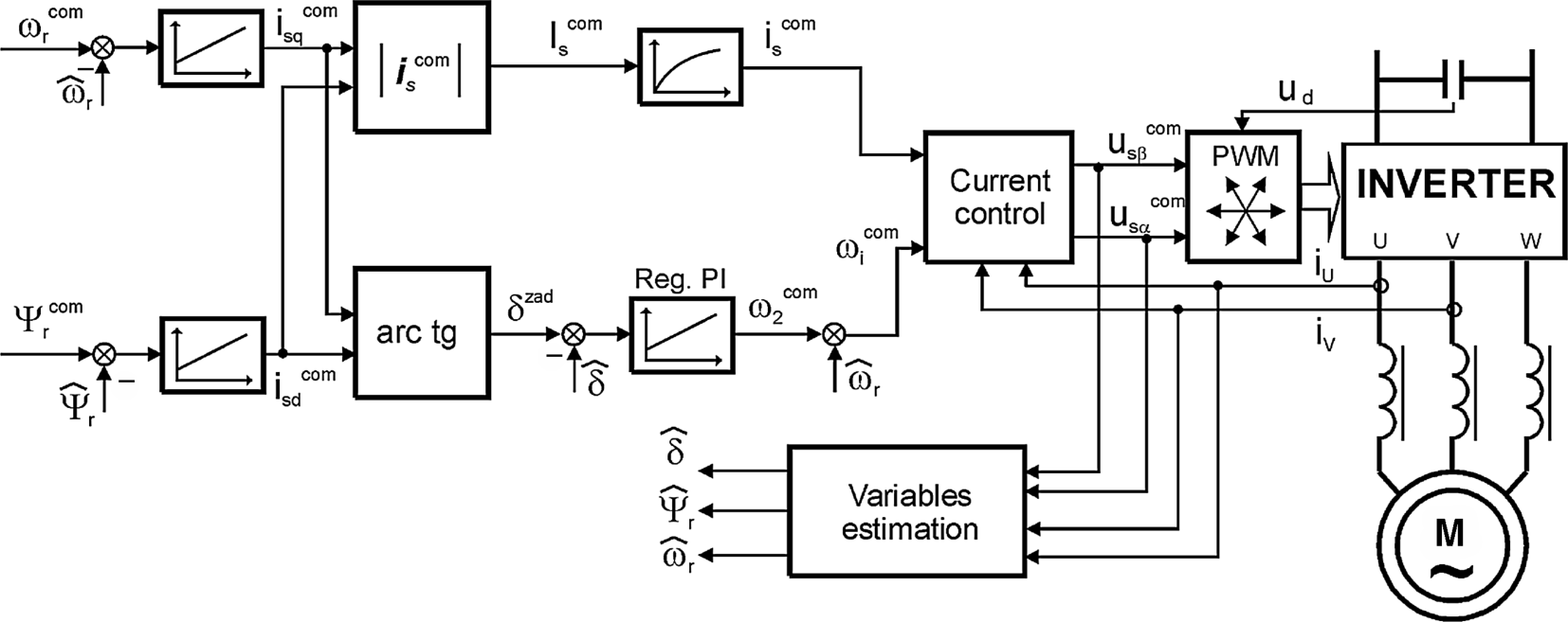
The FOC load angle control system base structure, based on equation (9.145), is presented in Figure 9.71.
Figure 9.71 Base structure of the FOC algorithm with load angle control (![]() denotes variables evaluated in estimation block)
denotes variables evaluated in estimation block)

In the control system shown in Figure 9.71, the measured variables are the inverter output currents and inverter DC link voltage. The motor currents and motor voltages are not measured. The load angle is controlled by commanding ...
Get High Performance Control of AC Drives with Matlab / Simulink Models now with the O’Reilly learning platform.
O’Reilly members experience books, live events, courses curated by job role, and more from O’Reilly and nearly 200 top publishers.

